14 replacement of parts – Glow-worm 24-38CXI Range User Manual
Page 45
45
0020013349-02
14 Replacement of Parts
14.22 Flow Sensor
For access, refer to section 14.1.
Refer to section 12.10 and drain the boiler hot water circuit.
Refer to diagram 14.17.
Remove the clip securing the filling loop tube to the domestic
water filter housing, see diagram 14.20.
Pull the tube forward to disengage it before rotating it down and
out of the way.
Undo the brass securing nut above the cold water inlet valve.
Remove the securing clip between the domestic water filter
housing and the flow sensor, see diagram 14.17.
Disengage the domestic water filter housing by lifting it up and
out.
Remove the electrical connection to the flow sensor.
Remove the securing clip between the flow sensor and the
hydroblock.
Remove flow sensor.
Fit new 'O' rings.
After replacing the flow sensor, open the cold-water isolation
valve and slowly open a hot water tap to remove air.
Close the hot water tap and check for any leaks.
14.23 Low Water Pressure Sensor
For access, refer to section 14.1.
Refer to section 12.9 and drain the boiler heating circuit.
Refer to diagram 14.18.
Disconnect the electrical lead by pushing up retaining tab to
withdraw the lead plug.
Remove the retaining clip to remove the low water pressure
sensor.
Fit new 'O' ring.
Fit the new low water pressure sensor. Refill vent and pressurise
the boiler.
Check for leaks.
14.24 Bypass
For access, refer to section 14.1.
Refer to section 12.9 and drain the boiler heating circuit.
Refer to diagram 14.19.
Remove the retaining clips to remove the bypass tube.
Fit new 'O' rings.
Replace the bypass tube, refill, vent and pressurise the boiler.
Check for leaks.
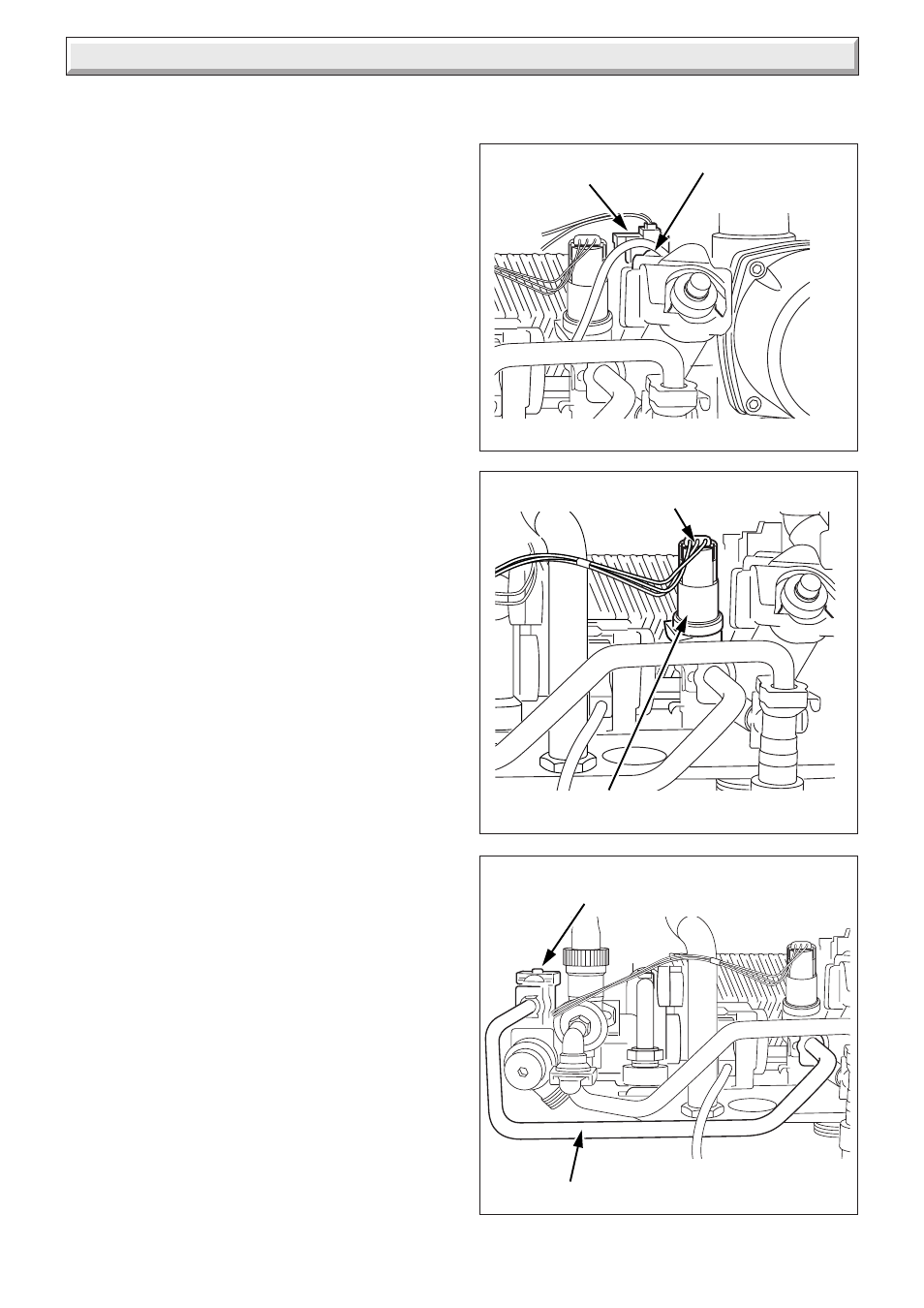
Diagram 14.17
FLOW SENSOR
RETAINING CLIP
11497
Diagram 14.18
LOW WATER
PRESSURE SENSOR
Diagram 14.19
BYPASS TUBE
ELECTRICAL
LEAD AND PLUG
AUTOMATIC BYPASS
VALVE
11476
12946