14 replacement of parts – Glow-worm 24-38CXI Range User Manual
Page 43
43
0020013349-02
14 Replacement of Parts
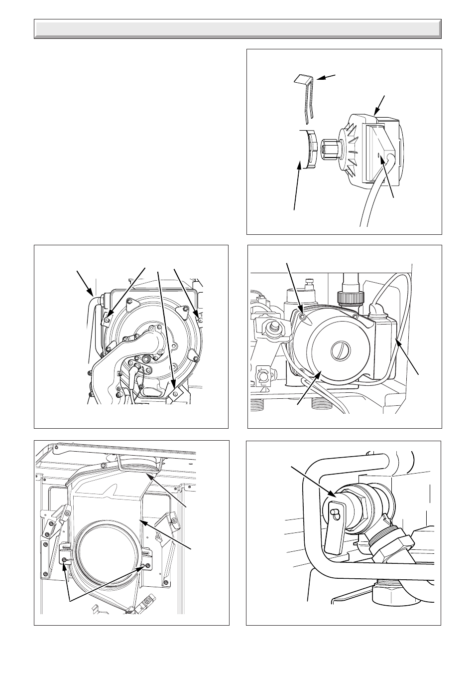
14.16 Safety Discharge Valve
For access, refer to section 14.1.
Refer to section 12.9 and drain the boiler heating circuit.
Refer to diagram 14.13.
Undo the safety discharge valve union and remove from the
pipework.
Remove the securing clip and withdraw the safety discharge
valve.
Fit new 'O' ring.
Refill, vent and pressurise the boiler.
Check for leaks.
Diagram 14.9
FLOW AND
RETURN PIPE
NUTS
SECURING SCREWS
AND CLAMPS
Diagram 14.10
FLUE
HOOD
BRACKET
SECURING
SCREWS
10066
DIVERTER VALVE
MOTOR
DIVERTER VALVE
Diagram 14.11
ELECTRICAL
PLUG)
RETAINING CLIP
(NOTE ORIENTATION)
11602
11490
FLUE
HOOD
Diagram 14.12
PUMP
HEAD
CAP HEAD SCREW (4)
CABLE
COVER
11496
Diagram 14.13
SAFETY
DISCHARGE
VALVE
11694
See also other documents in the category Glow-worm Water boiler:
- 12-38hxi Range (44 pages)
- 18-30sxi Range (48 pages)
- 23c (44 pages)
- 30ci Plus (56 pages)
- BBU 45/4 (32 pages)
- BBU 54/4 (32 pages)
- Betacom C (68 pages)
- Betacom2 (8 pages)
- Betacom2 (20 pages)
- Betacom2 (56 pages)
- Black Beauty 4 (20 pages)
- Chatsworth 4 (24 pages)
- Clearly Heat Recovery (20 pages)
- Clearly Heat Recovery (32 pages)
- Clearly Heat Pumps Envirosorb3 (28 pages)
- Clearly Heat Pumps Envirosorb2 (44 pages)
- Clearly Heat Pumps 7kW (44 pages)
- Clearly Heat Pumps 5kW (28 pages)
- Clearly Heat Pump 5kW (16 pages)
- Clearly Heat Pump 5 kW (32 pages)
- Clearly Heat Pump - Buffer Vessel (10 pages)
- Clearly Heat Pumps - Standalone Module System (40 pages)
- Clearly Heat Pumps - Standalone System (28 pages)
- Clearly Hybrid - Universal Module (20 pages)
- Clearly Hybrid - Universal Module System (36 pages)
- Clearly Hybrid - Compact Hydraulic Module (12 pages)
- Clearly Hybrid - Compact System (36 pages)
- Clearly Hybrid - Compact Hydraulic Module HB (16 pages)
- Clearly Hybrid - Back-up Module System (40 pages)
- Clearly Solar System Hydraulics (28 pages)
- Clearly Solar System (28 pages)
- Clearly Solar Controller (28 pages)
- Clearly Solar Horizontal On-Roof Collector (16 pages)
- Clearly Solar Vertical On-Roof Collector (16 pages)
- Clearly Solar Cylinders (32 pages)
- Clearly Solar - A-Frame (28 pages)
- Clearly Solar Horizontal In-Roof Collector (32 pages)
- Clearly Solar Vertical In-Roof Collector (44 pages)
- Clearly Solar Collector Container (8 pages)
- Climapro 1 (12 pages)
- Climapro2 RF (16 pages)
- Climapro2 RF (24 pages)
- Climapro2 RF (36 pages)
- Climapro2 RF (32 pages)