14 replacement of parts – Glow-worm 24-38CXI Range User Manual
Page 42
42
0020013349-02
14 Replacement of Parts
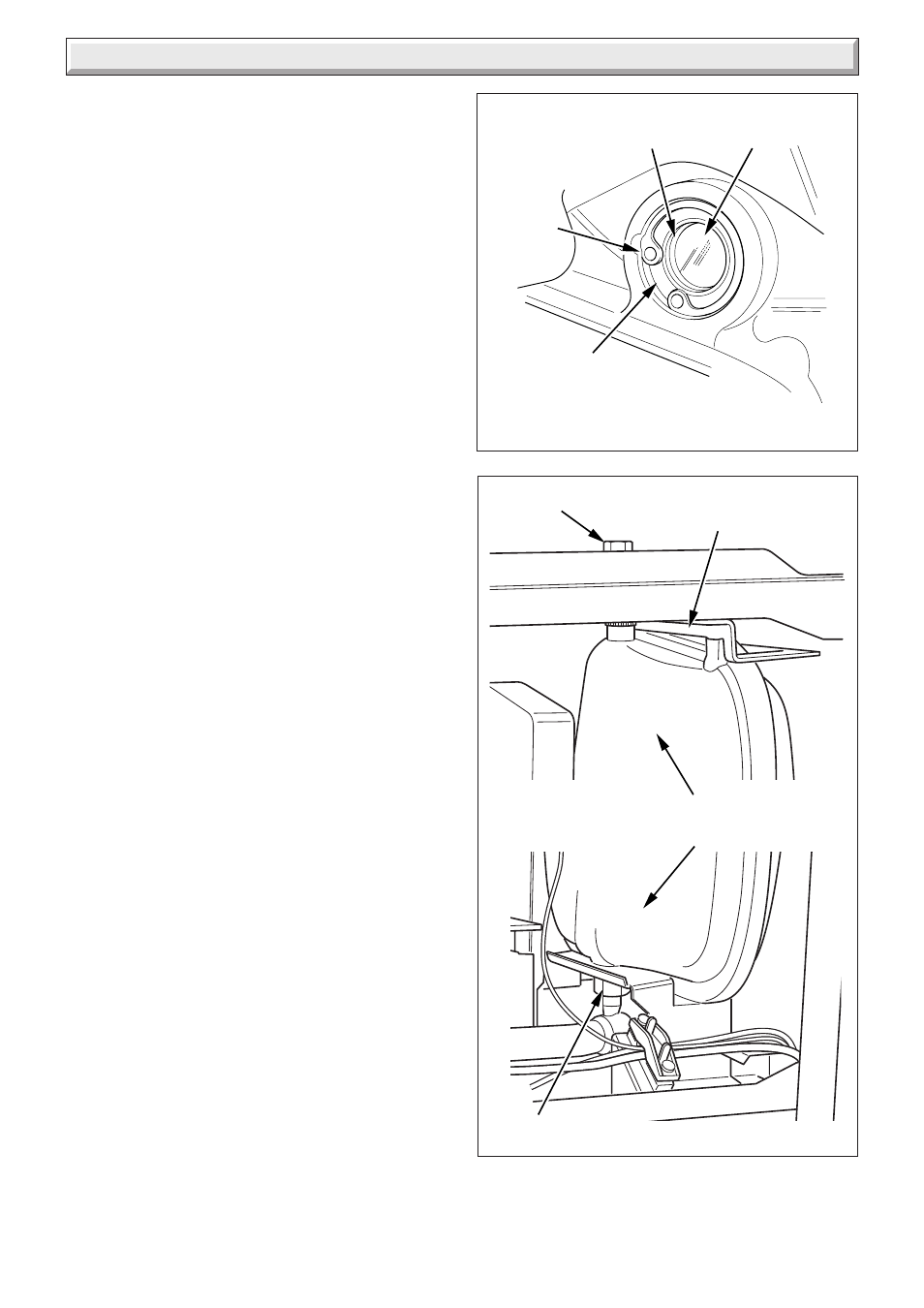
Fit a new gasket between the expansion vessel and coupling.
Refill, vent and pressurise the boiler.
Check for leaks.
14.12 Heat Exchanger
Refer to Manual Handling section on page 5.
For access, refer to section 14.1.
Refer to section 12.3 for removal of the fan, gas valve and burner
assembly.
Drain the boiler heating circuit, see section 12.9.
Drain the boiler hot water circuit, see section 12.10.
Remove the clip securing the clear condense pipe to heat
exchanger.
Pull to remove the clear condense pipe out of the bottom of the
heat exchanger.
Undo the two nuts of the flow and return pipes from the heat
exchanger.
Move the pipes away from the heat exchanger.
Loosen the three heat exchanger securing screws and clamps
(two at the top and one at the bottom) to remove the heat
exchanger, see diagram 14.9.
CAUTION: There will be water in the heat exchanger.
Remove condense pipe connector from bottom of heat
exchanger.
Carefully ease heat exchanger out.
14.13 Flue Hood
For access, refer to section 14.1.
Remove heat exchanger as per section 14.12.
Remove the two securing screws and pull the flue hood down
and away from the flue hood bracket and flue elbow, see
diagram 14.10.
14.14 Diverter Valve Motor
For access, refer to section 14.1.
Refer to diagram 14.11.
Remove the electrical plug.
Remove the retaining clip.
Ease the diverter valve motor from its housing and remove.
14.15 Pump (head only)
For access, refer to section 14.1.
Refer to section 12.9 and drain the boiler heating circuit.
Refer to diagram 14.12.
Remove the four cap head screws.
Carefully remove the pump head together with cable. Do not
strain cable.
Support the pump head, unscrew cable cover at the side of
pump head and take off.
Disconnect wiring from pump head.
Reconnect wiring to new pump head and fit cover.
Fit the new pump head with 'O' ring.
Refill, vent and pressurise the boiler.
Check for leaks.
Diagram 14.7
CIRCLIP
GLASS
STEEL
WASHER
FIBRE
WASHER
Diagram 14.8
SECURING
BOLT
COUPLING
UPPER SUPPORT
BRACKET
EXPANSION
VESSEL
11413
11488
11489