12 servicing – Glow-worm 24-38CXI Range User Manual
Page 33
33
0020013349-02
12 Servicing
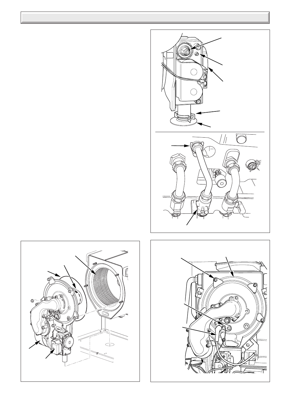
Withdraw the gas pipe from gas valve connection and remove.
NOTE: When replacing ensure that the sealing grommet,
situated below the gas valve is correctly re-seated.
Disconnect the gas valve electrical plug at the gas valve.
Disconnect the electrical leads from the fan.
Remove the five combustion chamber front retaining nuts, see
diagram 12.6.
Gently remove the fan, gas valve and burner assembly from the
combustion chamber, see diagram 12.4.
Clean the burner with a soft brush taking great care not to
damage the front insulation. DO NOT use wire or sharp
instruments to clean the holes of the burner.
Inspect the burner for any signs of damage.
Inspect the sealing rings and replace if necessary.
Removal of the burner is not necessary during a normal service.
NOTE: IF THE BURNER HAS TO BE REMOVED IT WILL
REQUIRE A NEW GASKET WHEN REFITTED.
12.4 Combustion Chamber and Heat
Exchanger
Refer to diagram 12.4.
Remove loose debris from combustion chamber using a soft
brush and vacuum cleaner. Carefully flush by spraying water
any remaining debris through the condensate trap (Ensure the
water is kept away from electrical components).
12.5 Condensate Drain
The condense drain does not normally need removing during
servicing.
To flush the condense drain carefully pour water into the heat
exchanger and check that water flows freely to drain.
If the condense drain is blocked refer to section 14.33 for
removal.
Diagram 12.4
BURNER
COMBUSTION CHAMBER
FAN
GAS VALVE
SEALING
RING
11502
Diagram 12.5
GAS VALVE
GAS PIPE
RETAINING CLIP
SEALING GROMMET
GAS SERVICE COCK
GAS PIPE
RETAINING
CLIP
12402
12770
THROTTLE
OFFSET
ADJUSTMENT
HEAT
EXCHANGER
SECURING NUT
(5 OFF)
ELECTRODE
LEAD
Diagram 12.6
SPADE
CONNECTOR
11490