12 servicing – Glow-worm 24-38CXI Range User Manual
Page 32
32
0020013349-02
12 Servicing
Important Notes
To ensure the continued efficient and safe operation of the
boiler it is recommended that it is checked and serviced at
regular intervals. The frequency of servicing will depend upon
the particular installation and usage, but in general once a year
should be enough.
It is the Law that any servicing is carried out by a competent
person.
When replacing a part on this appliance, use only spare parts
that you can be assured conform to the safety and performance
specification that we require. Do not use reconditioned or copy
parts that have not been clearly authorised by Glow-worm.
12.1 General
Refer to Table 2 Section 1 Technical Information. Measurement
of the products of combustion can be achieved by connection
of a probe to the combustion analyser test point, see diagram
12.1.
IMPORTANT NOTE: Products of combustion will be discharged
when the cap is removed. It is important to replace the cap
immediately.
Before commencing with a service or replacement of parts the
boiler should be isolated from the electrical supply and the gas
supply should be turned off at the gas isolation valve, see
diagram 7.1.
All routine servicing requirements can be achieved by the
removal of the front panel and inner panel only. To remove
simply undo the two screws on the underside of the front panel
and lift off, see diagram 11.1. Undo the two screws on the front
of inner panel and lift off, see diagram 11.1.
Unless stated otherwise any part removed during servicing
should be replaced in the reverse order to removal.
Servicing should always include the removal of any debris from
the condensate pipe and siphon.
After completing any servicing of gas carrying components,
ALWAYS test for gas soundness and carry out a functional test
of the controls.
Testing Flue Gases: If any doubt exists that the flue products
are not exhausting correctly, investigate by use of a gas
analyser (FGA).
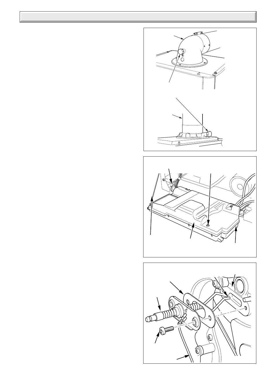
12.2 Spark Electrode
Disconnect the electrode lead and two securing screws.
Withdraw the spark electrode carefully from the combustion
chamber, see diagram 12.3 and 12.6.
Inspect the tips for damage.
Clean away any debris and check the spark gap is 3.5 to 4.5
mm.
Check the electrode gasket for signs of damage and replace if
necessary.
12.3 Burner
Drop down the control panel into the service position, see
diagram 12.2.
Disconnect the gas supply at the gas service cock, see diagram
7.1.
Remove the two gas pipe retaining clips, one located below gas
valve and the other one located on the underside of the boiler
chassis, see diagram 12.5.
Pull sealing grommet down gas pipe, see diagram 12.5.
Push the gas pipe upwards further into gas valve connection
and then rotate anti-clockwise (looking down) until the gas pipe
end is over the large hole in boiler chassis, see diagram 12.5.
SECURING
SCREW (2 OFF)
SPARK
GAP 3.5 to 4.5
HEAT
EXCHANGER
ELECTRODE
GASKET
Diagram 12.1
EARTH LEAD
11410
9808
REAR PANEL
TORX
SCREWS (3)
CONTROL BOX
RETAINING
CORD
RETAINING
SLOTS
Diagram 12.2
FLUE ELBOW
COMBUSTION
ANALYSER
TEST POINT
FLUE DUCT
EXTENSION
12853
Diagram 12.3