14 replacement of parts – Glow-worm 24-38CXI Range User Manual
Page 44
44
0020013349-02
Diagram 14.16
AUTOMATIC
AIR VENT
Diagram 14.15
RETURN
PIPE
FLOW
PIPE
RETURN
THERMISTOR
OVERHEAT
THERMOSTAT
FLOW
THERMISTOR
11498
11503
14 Replacement of Parts
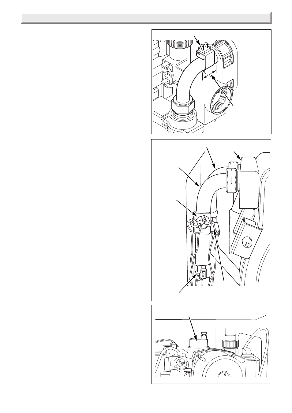
14.17 Domestic Hot Water Thermistor
For access, refer to section 14.1.
Refer to section 12.10 and drain the boiler domestic hot water
circuit.
Refer to diagram 14.14.
Disconnect the domestic hot water thermistor electrical
connections
Remove hot water thermistor and retaining clip.
Remove domestic hot water thermistor from clip.
NOTE: When reconnecting electrical connections, polarity is
not important.
Carry out a functional test of the controls.
14.18 Heating Flow Thermistor
For access, refer to section 14.1.
Refer to diagram 14.15.
Remove the electrical connections from the thermistor.
Remove the retaining clip from the flow pipe.
NOTE: When reconnecting, the polarity of the wiring to
thermistors is not mportant.
14.19 Heating Return Thermistor
For access, refer to section 14.1.
Refer to diagram 14.15.
Remove the electrical connections from the thermistor.
Remove the retaining clip from the return pipe.
NOTE: When reconnecting, the polarity of the wiring to
thermistors is not important.
14.20 Overheat Thermostat
For access, refer to section 14.1.
Refer to diagram 14.15.
Remove the electrical connections from the overheat thermostat.
Remove the retaining clip from the flow pipe.
Remove the overheat thermostat from the retaining clip.
NOTE: When fitting new thermostat, please ensure that it is
located correctly onto the flat area of the pipe and the retaining
clip is secure.
14.21 Automatic Air Vent
For access, refer to section 14.1.
Refer to section 12.9 and drain the boiler heating circuit.
Refer to diagram 14.16.
Unscrew the automatic air vent.
Fit the new automatic air vent and 'O' ring ensuring the vent cap
is left loose.
Refill, vent and pressurise the boiler.
Check for leaks.
HEAT
EXCHANGER
Diagram 14.14
DOMESTIC HOT WATER THERMISTOR
NOTE: Position
thermistor within
the area indicated
12938