11 commissioning – Glow-worm 24-38CXI Range User Manual
Page 29
29
0020013349-02
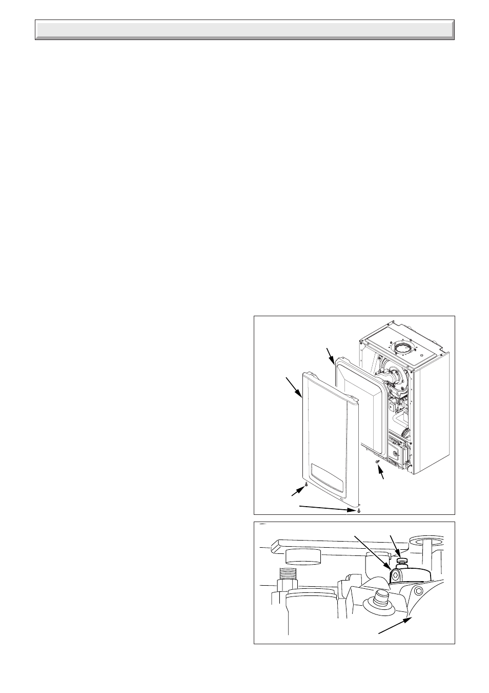
Diagram 11.2
CAP
AUTOMATIC AIR VENT
PUMP
12762
Please ensure the "Benchmark" logbook is completed and left
with the user and the magnetic lighting instruction label is
placed on the surface of the boiler casing.
LPG CONVERSION - 30cxi only
NOTE: Steps 11.1 to 11.3 will need to be completed before the
appliance can be converted.
The 30cxi can be converted to run on LPG-Propane (G31).
This conversion should only be carried out by a competent
person.
During the conversion to Propane use of a suitable flue gas
analyser is necessary.
As an option a chargeable boiler only commissioning service
can be provided by Glow-worm Service by calling telephone
No. 01773 828100.
Tools required to make the conversion are a 2mm Allen key and
an electricians screwdriver.
Ensure that the appliance supply pressure = 37mbar.
(1) Access the gas valve.
(2) Refer to diagram 11.4 and turn the gas valve throttle fully
clockwise.
(3) Turn the throttle back anti-clockwise by 5
1
/
2
turns.
(4) Ensure that the gas analyser is set to the correct fuel
setting - Propane.
(5) Attach combustion analyser to the combustion test point.
See diagram 12.1.
(6) Unclip the controls fascia to reveal the service potentiometer
on the rear of the user interface. See diagram 12.7.
(7) Turn on the mains electrical supply and turn on the gas
service cock. Switch the boiler on.
(8) Ensure external controls are calling for heat. The boiler
should fire automatically.
(9) Using an electrical screwdriver, rotate the service
potentiometer to the mid point or 3 o’clock position. See
diagram 12.7. The fan speed should now reduce to minimum
and ‘12’ should be shown flashing on the digital display.
Check the CO
2
value. If necessary refer to diagram 11.4
and using a 2mm allen key carefully adjust the offset screw
until a CO
2
reading of 10.5% ± 0.2% is achieved. Turning
the offset screw clockwise increases the CO
2
reading.
(10) After setting combustion, rotate the service
potentiometer fully anti-clockwise so that the display
indicates the water temperature. Check that the CO
2
combustion remains between 9.8% and 10.8% CO
2
. Further
adjustment should not be necessary, however if required,
carefully adjust the gas valve throttle (see diagram 11.4)
until this is achieved.
(11) Remove analyser probe from the test point and replace the
cap. Refit the control panel.
(12) Fit the LPG conversion label supplied in the documentation
pack to the inner front panel alongside the data
label. Refit the inner door and outer door.
11.1 Filling Domestic Water Circuit
Fully open any valves in the domestic water supply to the boiler.
Open the domestic water isolation valve, slot in line with the
length of the valve, see diagram 7.1.
Open all hot water taps in turn and close them when water flows.
Check for water soundness of the complete domestic water
system.
11 Commissioning
The water flow rate is restricted to a maximum 10 l/min (24cxi)
12 l/min (30cxi) and15.5 l/min (38cxi) by a restrictor fitted during
boiler installation, see diagram 7.1.
11.2 Filling the Heating Circuit
Refer to section 4 to fill the system.
Open the two central heating isolating valves and domestic cold
water inlet valve, slots in line with the length of the valve, see
diagram 7.1
To enable the system pressure to be viewed, turn the Central
heating temperature knob and hot water temperature knob to
the off position.
Turn the mains electricity supply on to the appliance and ensure
that the mains switch on the appliance fascia is set to the on
position.
The system pressure is displayed on the controls panel fascia
of the appliance, see diagram 1 of the User Instructions.
Fill the system until the pressure on the display reads at least
1.0bar. Note that on filling the system a small amount of water
may be discharged from the reduced pressure zone valve, see
diagram 4.2.
Remove the two inner casing panel securing screws, lift the
panel off the retaining lugs, refer diagram 11.1.
Make sure that the automatic air vent works correctly and that
the black cap is loosely fitted to allow air to escape, see diagram
11.2.
Check the heating system and boiler connections for water
soundness.
Diagram 11.1
INNER
CASING
PANEL
CASING
PANEL
12353
SECURING
SCREWS
SECURING
SCREW (2)