10 electrical connection, 1 mains cable, 2 voltage free system controls – Glow-worm 24-38CXI Range User Manual
Page 27: Voltage free room thermostat programmer, Boiler
27
0020013349-02
CONTROL
PANEL REAR
COVER
SECURING
SCREW (3)
10181
CABLE
EXIT
CONTROL
PANEL
REAR
COVER
VOLTAGE FREE
HEATING
CONTROLS
CONNECTION
WIRE
LINK (E)
11506
10 Electrical Connection
WARNING: This appliance must be earthed.
This appliance must be wired in accordance with these
instructions. Any fault arising from incorrect wiring cannot be
put right under the terms of the Glow-worm guarantee.
All system components must be of an approved type.
Electrical components have been tested to meet the equivalent
requirements of the BEAB.
Do not interrupt the mains supply with a time switch or
programmer.
Connection of the whole electrical system and any heating
system controls to the electrical supply must be through a
common isolator.
Isolation should preferably be by a double pole switched fused
spur box having a minimum contact separation of 3mm on each
pole. The fused spur box should be readily accessible and
preferably adjacent to the boiler. It should be identified as to its
use.
A fused three pin plug and shuttered socket outlet may be used
instead of a fused spur box provided that:
a) They are not used in a room containing a fixed bath or
shower.
b) Both the plug and socket comply with the current issue of
BS1363.
10.1 Mains Cable
Important: If a replacement supply cable is required it must be
purchased. Part No. S1008600.
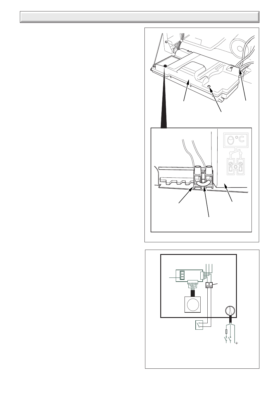
10.2 Voltage Free System Controls
WARNING: UNDER NO CIRCUMSTANCES MUST ANY
MAINS VOLTAGE BE APPLIED TO ANY OF THE TERMINALS
ON THE VOLTAGE FREE HEATING CONTROLS
CONNECTION PLUG.
This boiler will operate continuously on heating as supplied, if
the wire link (E), fitted between the two terminals of the heating
controls connection, is left in place, see diagram 10.1.
System heating controls e.g. Room thermostat, should be fitted
in accordance with the rules in force.
Refer to diagram 10.2.
Diagram 10.2
Diagram 10.1
230V~ 50Hz
PERMANENT
MAINS SUPPLY
3 AMP FUSE
DOUBLE POLE
ISOLATOR
L N E
ROOM
THERMOSTAT
DO NOT
CONNECT
X
VOLTAGE FREE
ROOM THERMOSTAT
PROGRAMMER
3
2
1
TO MAIN PCB
CONNECTOR J15
VOLTAGE FREE
HEATING
CONTROLS
CONNECTION
(ON CONTROLS
BOX COVER)
ON/OFF
SWITCH
CONTROLS
INTERFACE PCB
BOILER
PROGRAMMER
12442