2 ace-b2019/a h/w information, 1 ace-b2019/a layout (top side) – Acrosser ACE-MINI User Manual
Page 28
Revision: 1.0
28
3.2 ACE-B2019/A H/W Information
This section describes the installation of ACE-B2019/A. At first, it shows the function
diagram and the layout of ACE-B2019(A). It then describes the unpacking information which
you should read carefully, as well as the jumper/switch settings for the ACE-B2019/A
configuration.
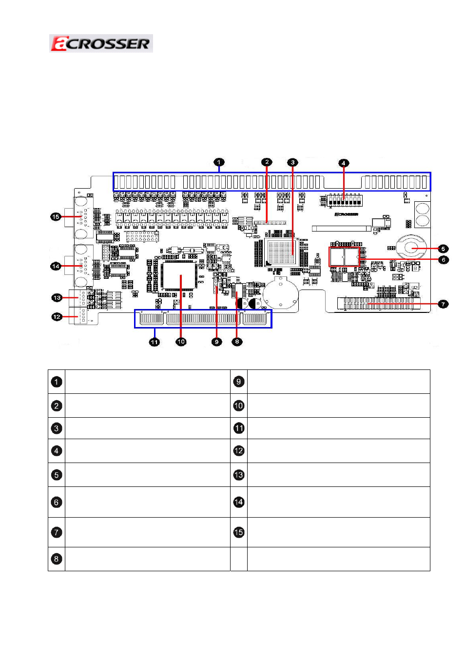
3.2.1 ACE-B2019/A LAYOUT (Top side)
Note:* for ACE-B2019A only.
FRUIT1
72-Pin Gold Finger & 20-Pin Gold Finger.
JP1
AGA Programming Pin Header.
*
CN4
FPGA Programming Pin Header.
U50
OXuPCI954 UART Controller IC.
*
U13
AGC (Acrosser Gaming Core).
PCI
PCI Gold Finger.
SW4
Intrusion Log Switch.
ccTalk2
ccTalk Connector (Signal share with COM3).
*
U3
i-Button Holder.
*
ccTalk1
ccTalk Connector (Signal share with COM2).
*
U17, U18
SRAM A. SRAM B.
(ACE-B2019 Only has 512KB SRAM A )
COM2
RS232 Serial Ports COM2.
*
CN6
Reel Controller Connector (44pin mini-IDE Reel
Connector connects to AR-B2009).*
COM1
RS232 Serial Ports COM1.
*
U5
AGA (Acrosser Gaming Engine).
*