Figure 3, Installing the battery – Bolens 130-527-000 User Manual
Page 8
Attention! The text in this document has been recognized automatically. To view the original document, you can use the "Original mode".
Shift
Lever
Locks.
Transmissior
Cover
FIGURE 3.
Red
(Positive) Black
Shift
Cable (Negative)
Lever !^P^itive^\
vTerminal^
Hold-Down
Rod (E)
FIGURE 4.
Drain
Tube
INSTALLING THE BATTERY
1. Place the shift lever in the “N” (neutral) position.
Unscrew the gear shift lever knob.
2. Push down and turn the locks on the transmission
----- cover. See figure 3.
3. Lift the transmission cover. Unplug the safety wire
from beneath the transmission cover. Remove
transmission cover.
4. Move the shift lever all the way to the left. See
figure 4.
5. Hook the hold down rods (E) into the holes in the
frame and lay them off to the sides.
6. Place the battery in the lawn tractor so that the
positive terminal is towards the left side of the unit.
Feed the end of the battery drain tube through the
hole provided in this frame. See figure 4.
Slide the hex nut (provided with battery hardware)
into the positive (+) terminal. Place the positive
(heavy red wire) cable on the positive terminal.
Secure with bolt provided. See figure 4.
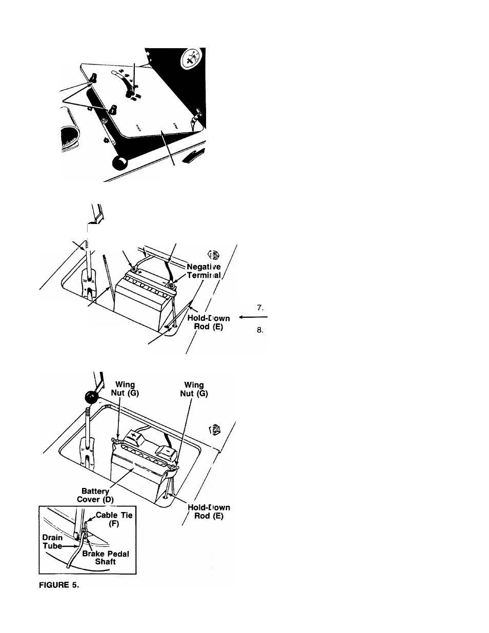
Slide the hex nut (provided with battery hardware)
into the negative (-) terminal. Place the negative
(heavy black wire) cable on the negative terminal.
Secure with bolt provided.
10. Place the battery cover (D) in position over the bat
tery and one hold-down rod. Secure with wing nut
(G). Attach other hold-down rod to the other side
----- of battery cover in the same manner. See figure 5.
11. Using cable tie (F), secure battery drain tube to the
brake pedal shaft assembly. Cut off excess end.
See figure 5, inset.