Operation, Ignition, Brake – Bolens 130-527-000 User Manual
Page 11: Ignition switch, Ammeter (optional), Safety interlock system, Light switch (optional), Clutch parking brake pedal, Caution, Controls
Attention! The text in this document has been recognized automatically. To view the original document, you can use the "Original mode".
OPERATION
V
CAUTION
■
READ OPERATOR'S iv-IANUAL(S) • NEVER CARRY CHILDREN
■
KNOW LOCATION AND FUNCTION OF ALL CONTROLS
' KEEP SAFETY DEVICES (GUARDS. SHIELDS AND SWITCHES)
IN PLACE AND WORKING
' REMOVE OBJECTS THAT COULD BE THROWN BY BLADE(S)
' DO NOT OPERATE THE UNIT WHEN CHILDREN AND OTHERS
ARE AROUND
' ALWAYS LOOK BEHIND THE UNIT BEFORE BACKING UP
’ DO NOT OPERATE THE UNIT WHERE IT COULD SLIP OR TIP
' IF THE UNIT STOPS GOING UPHILL, STOP BLADE(S) AND BACK
SLOWLY DOWNHILL
' BE SURE BLADE(S) AND ENGINE ARE STOPPED BEEORE PLAC
ING HANDS OR FEET NEAR BLADEl'S)
■
BEFORE LEAVING OPERATOR'S POSITION, DISENGAGE THE
BLADE(S). PLACE THE SHIFT LEVER IN NEUTRAL. ENGAGE THE
PARKING BRAKE. SHUT ENGINE OFF AND REMOVE THE KEY,
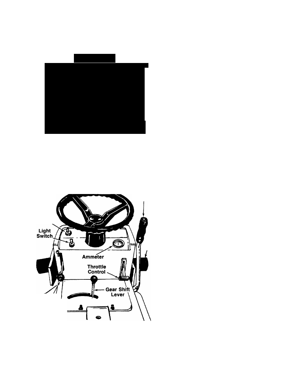
CONTROLS
Throttle Control
The throttle control is used to regulate the engine speed
and choke the engine. The engine should be operated
from 3/4 to full throttle when operating the cutting deck.
See figure 10.
Lift Lever
Ignition
Switch
Brake
Pedai
Blade
Engagement
/ Lever ^
FIGURE 10.
Ignition Switch
The ignition switch is located on the right side of the
dashboard. Turn the key to the START position to start
the engine. When the engine is running, leave the key
in the ON position. To stop the engine, turn the key to
the OFF position
A
WARNING: Remove the key from the lawn
tractor when the tractor is not in use to
prevent accidental starting.
Ammeter (Optional)
The ammeter registers the rate of battery charge or
discharge. The ammeter should register about 3 amps
on the plus (+) side with the engine running fast. The
head lamps operate directly from the engine and do
not register on the ammeter.
Safety Interlock System
Interlock safety switches are located on the clutch
pedal, the blade engagement lever and gear shift lever.
Before the engine will start, the clutch pedal must be
depressed all the way and the blade engagement lever
must be in the disengaged position.
Before the unit can be shifted into reverse, the blade
engagement lever must be in the disengaged position.
The safety interlock system has another switch located
on the rear of the lawn tractor that is activated when
the grass catcher is attached to the tractor. If you
remove the grass catcher or attempt to dump the grass
without shutting off the blade, the engine will stop.
A
WARNING: Do not operate the lawn trac
tor if the interlock system is maifunction-
ing because it is a safety device,
designed for protection.
Light Switch (Optional)
To turn on head lamps, push the switch marked
“Lights” located on the left side of the dashboard. See
figure 10.
NOTE: The head lamps operate directly from the alter
nator and only operate when the engine is running.
Clutch Parking Brake Pedal
The clutch parking brake pedal is located on the left
side of the lawn tractor and is used to disengage the
drive mechanism. Depressing the clutch parking brake
pedal will disengage the drive and APPLY THE DISC
BRAKE TO THE REAR WHEELS. The clutch brake
pedal must be depressed when you come to a stop,
shift gears or start the engine. See figure 11.
11