Interface specifications – Citizen Systems CBM-253 User Manual
Page 38
CBM-253 User’s Manual
26
CITIZEN
5.
INTERFACE SPECIFICATIONS
5.1 Serial interface
Specifications (Conform to RS-232C)
Synchronizing system
: Asynchronous system
Handshaking
: DTR/DSR control or Xon/Xoff control
Baud rates
: 1200, 4800, 9600, 19200 (Selected by the user)
Data length
: 7 or 8 bit length (Selected by the user)
Parity
: Odd/Even/None (Selected by the user)
Signal level
: Mark= -3 ~ -15V Logic '1'
: Space = +3 ~ +15V Logic '0'
Compatible interface connectors
Printer side
: 25-pin connector
17-13250 (DDK) equivalent product
Cable side
: 25-pin connector
17-23250 (DDK) equivalent product
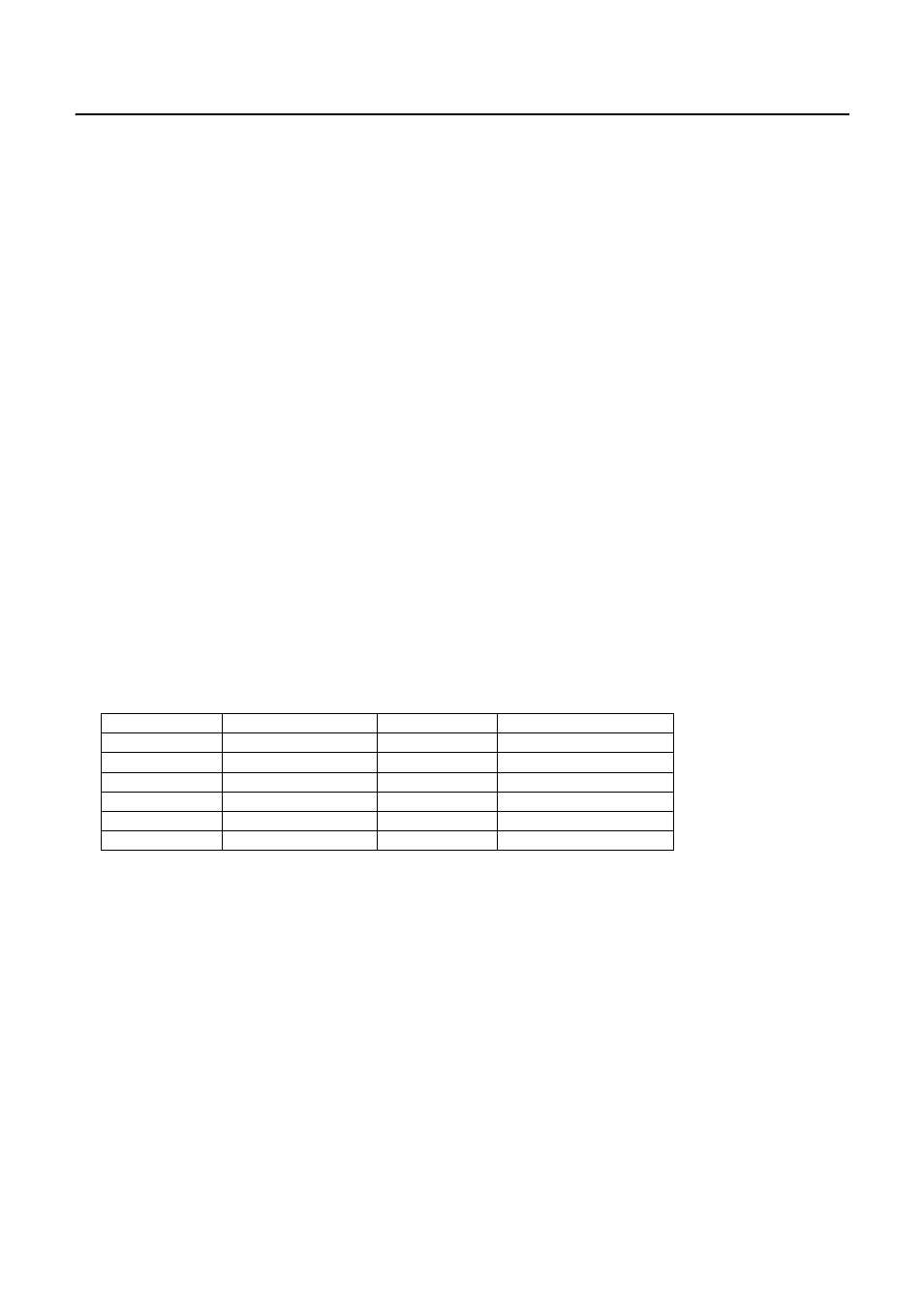
Connector's pin configuration
Connector pin
Signal name
Input/output
Function
1 FG –
Frame
ground
2 T
X
D Output
Sending
data
3 R
X
D Input
Receiving
data
6 DSR
Input
Data
set
ready
20
DTR
Output
Data terminal ready
7 SG –
Signal
ground
Note: Shielded type cables should be used.
Explanation of input and output signals
(1) RxD
This is the serial receiving data signal. On the occurrence of framing errors, overrun errors or parity errors,
this data will either be rejected or printed as ' ?'. according to the DSW2-7 switch condition.