Assembly (cont.), Warning, Fig. 5 – Bolens 13067 User Manual
Page 9: Fig. 6
Attention! The text in this document has been recognized automatically. To view the original document, you can use the "Original mode".
ASSEMBLY (Cont.)
Fig. 5
M
/
/
K
\ X
N X
j
Fig. 6
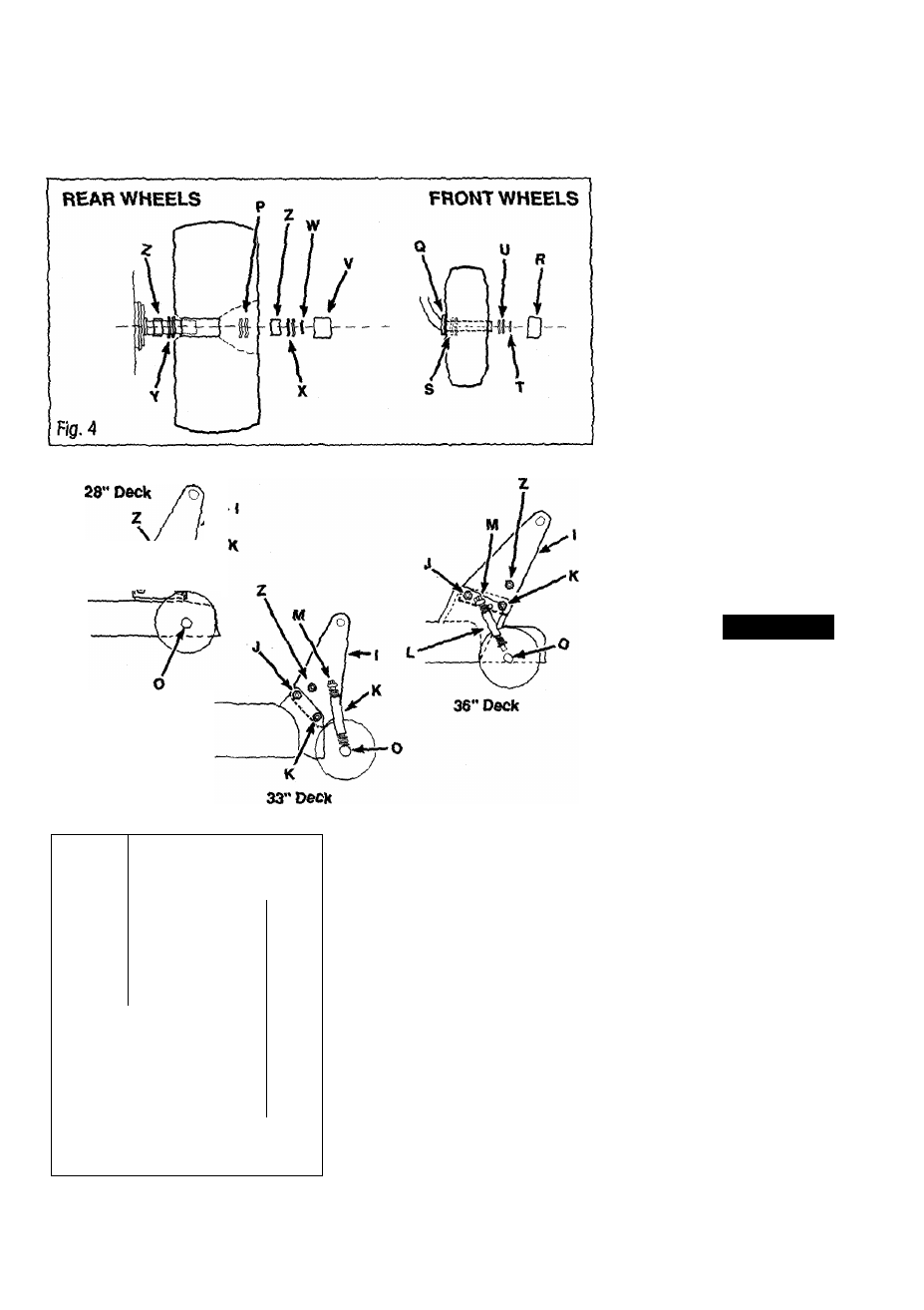
3. Attach shoulder bolts (Z) to lift plates.
Insert bolt from the inside. Secure with
nut.
GAGE WHEEL ASSEMBLY (If
required)
1, Slide a spacer, a gage wheel, and a 1/2
flat washer onto a gage wheel axle.
Secure with a cotter pin. Repeat on the
other side.
MOWER DECK INSTALLAYIOH
28" Mower Deck Installation
The 28" mower deck is shipped assembled
on your riding mower, with the
discharge
chute removed (this discharge chute
WUST be installed on the deck before
using the mower). Some adjustment of
the mower deck
may
also be required (See
page 14).
MOWER DECK LIFT PLATE
ASSEMBLY (It required)
1. 33" DECKS: Place lift piate (I) on
inside of bracket on mower
deck (See
Fig.S).
28” & 36" DECKS: Place lift plate
(I) on
inside
of bracket on mower deck
(See fig. 5).
2. Secure with flange screws & nuts al
(J)
& (K). A/cris
sfra(//cf face toward the
inside of frame.
3. 33" & 36" DECKS: Place pivot
(M)
into desired height setting hole in lift plate
(I) and
secure wiSi washer and spring pin.
See GAGE
WHEBL ADJUSTMENT to
determine proper height.
WARNiNG!
TO HELP PBEVEHT PERSOMAL INJURY
FROM OBJECTS THROWN BY THE
MOWER DECK BLADE, THE
mSCHAROE CHUTE MUST BE
INSTALLED ON THE DECK.
FAILURE TO FOLLOW THIS
INSTRUCTION COULD RESULT IN
PERSONAL INJURY OR PROPERTY
DAMAGE.
NOTE: FOR SHIPPING PURPOSES
ONLY, A TEMPORARY SHIELD HAS
BEEN INSTALLED IN THE DISCHARGE
OPENING ON THE MOWER DECK
1, Remove bolts holding temporary shield
in discharge opening. Remove shield and
discard.
2. Loosely
attach ends of
discharge chute
(M, Fig. 6) inside discharge opening with
two 5/16-18 X 3/4 flange screws
and 5/16-
18 tlange nuts (N). The nuts should be on
top.