Tractor maintenance engine, Interlock system test, Warning – Bolens 13067 User Manual
Page 23: Tractor maintenance, Maintenance
Attention! The text in this document has been recognized automatically. To view the original document, you can use the "Original mode".
MAINTENANCE
TRACTOR MAINTENANCE
Engine
FOR SPECIFIC ENGINE MAINTENANCE
INSTRUCTIONS. REFER TO ENGINE OWNERS
MANUAL SUPPLIED WITH THE RIDING
MOWER. THE ENGINE OWNERS MANUAL
INCLUDES INSTRUCTIONS FOR CHECKING
ENGINE OIL LEVEL. CHANGING ENGINE OIL.
INSPECTING AND CLEANING ENGINE AIR
FILTER. IGNITION SYSTEM MAINTENANCE.
AND OTHER IMPORTANT ENGINE
MAINTENANCE INFORMATION. FOR
FURTHER REPAIRS. CONTACT YOUR LOCAL
BOLENSf^ DEALER.
Lubrication
Refer to Maintenance Chart on Page 32 for
lubrication instructions.
Interlock System Test
This riding mower is equipped with an
interlock system. This system prevents the
operator from starting the engine, if:
1. ) ...there is no one in the seat.
2. ) ...the brake pedal is not depressed.
3. ) ...the mower blade drive lever is in the
engaged position.
WARNING!
IF THE INTERLOCK SYSTEM DOES NOT
FUNCTION PROPERLY, SHUT THE
ENGINE OFF, APPLY THE PARKING
BRAKE, ALLOW THE ENGINE TO COOL,
DISCONNECT THE SPARK PLUG WIRE
AND PREVENT IT FROM TOUCHING
THE SPARK PLUG, AND REMOVE THE
KEY FROM THE KEYSWITCH. DO NOT
USE THE RIDING MOWER UNTIL THE
INTERLOCK SYSTEM IS REPAIRED.
FAILURE TO FOLLOW THIS WARNING
COULD RESULT IN PERSONAL INJURY
OR PROPERTY DAMAGE.
See
Interlock System Test
on page
20, in the CONTROLS AND
OPERATION section to perform this test.
Brake Adjustment
WARNING!
BEFORE ADJUSTING THE BRAKE,
SHUT THE ENGINE OFF, BLOCK THE
WHEELS, ALLOW THE ENGINE TO
COOL, DISCONNECT THE SPARK PLUG
WIRE AND PREVENT IT FRDM
TOUCHING THE SPARK PLUG, AND
REMOVE THE KEY FROM THE
KEYSWITCH.
FAILURE TO FOLLOW THIS WARNING
COULD RESULT IN PERSONAL INJURY
OR PROPERTY DAMAGE.
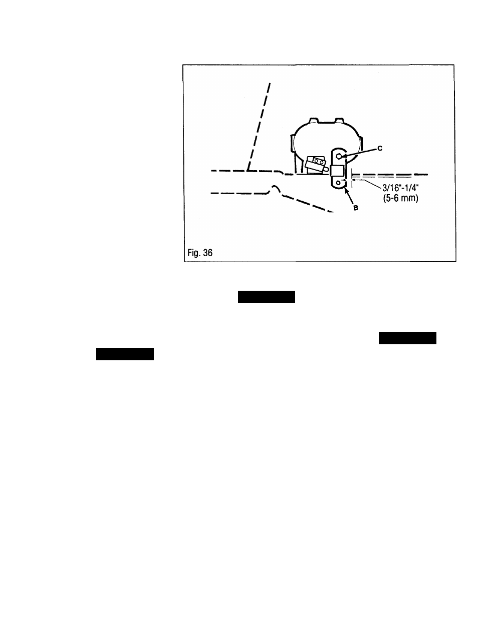
1. Lift seat and seat support up to gain
access to the side of transmission.
2. Turn hex nuts (C, Fig. 36) holding
brake lever to left-hand side of
transmission to remove any play from the
brake system.
3. Have an assistant push firmly on brake
pedal. Adjust until a gap of 3/16" (5 mm)
to 1/4" (6 mm) exists between front edge
of brake lever (B) and forward edge of slot
in frame the brake lever goes down
through.
NOTE: DO NOTOVER-TIGHTENNUTS
(C) OR THE BRAKE WILL DRAG AND
OVERHEAT.
Transmission Drive Beit
Repiacement
A
WARNING!
BEFORE REMOVING THE TRANSMIS
SION DRIVE BELT, SHUT THE ENGINE
OFF, BLOCK THE RIDING MOWER’S
WHEELS, ALLOW THE ENGINE TO
COOL, DISCONNECT THE SPARK PLUG
WIRE AND PREVENT IT FROM
TOUCHING THE SPARK PLUG, AND
REMOVE THE KEY FROM THE
KEYSWITCH.
FAILURE TO FOLLOW THIS WARNING
COULD RESULT IN PERSONAL INJURY
OR PROPERTY DAMAGE.
1. Remove mower deck.
See Mower
Deck Removal, page 25.
2. Move transmission shift lever to N
(Neutral).
3. Remove old transmission drive belt,
and discard.
23