Assembly (coni.) – Bolens 13067 User Manual
Page 12
Attention! The text in this document has been recognized automatically. To view the original document, you can use the "Original mode".
ASSEMBLY (Coni.)
RIDER PREPARATION FOR
DIFFERENT SIZED DECKS
28" and 36" decks require a different set
up of the riding mower than the 33" deck.
Set-up for the two configurations is
described below.
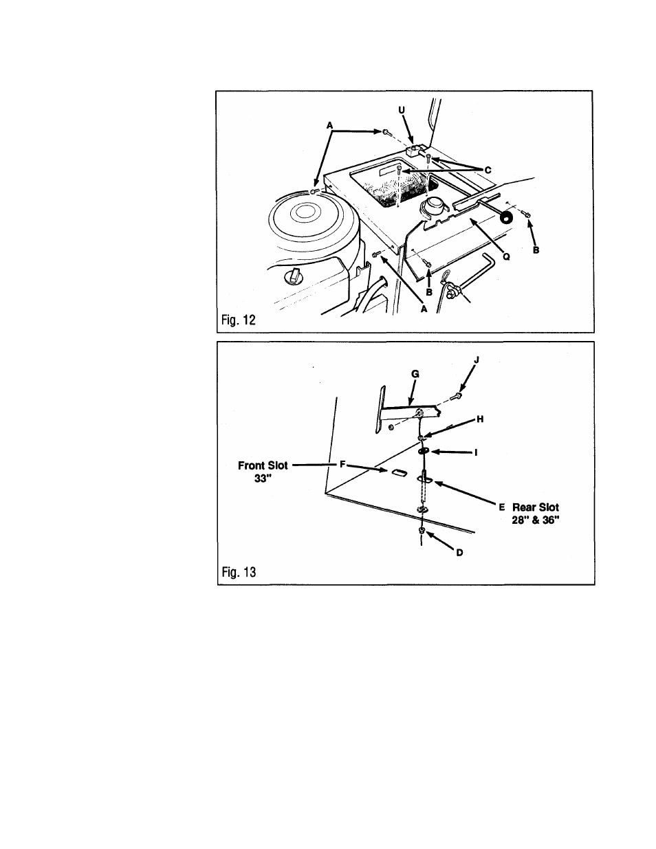
Remove Seat Support Cover
1. Lift seat.
2. Unscrew and remove shift knob.
3. Remove screws (B, Fig. 12) and
remove shift quadrant.
4. Unplug seat switch.
5. Remove screws (U) and pull seat
support from seat support cover.
6. Remove remaining 3 screws (A)
securing seat support cover. Remove 2
screws (C) securing gas tank to seat
support cover. Remove seat support
cover.
Install Mower Blade Drive
Cable
1. Thread nut (D, Fig. 13) downward on
cable threads until it stops.
2. Thread nut (H) and washer (I) upward
and off cable assembly.
3.
28” & 36" DECKS ONLY:
Insert
cable, nut (H) and washer (I) upward
through rear slot (E) in frame.
33" DECKS ONLY:
Insert cable, nut
(H) and washer (I) upward through front
slot (F) in frame.
4. Place nut (H) and washer (I) at top of
slot and screw down tightly, securing
cable assembly to frame.
5. Connect cable to the mower blade drive
(PTO) lever (G). Fasten cable to the right
side of PTO lever when facing toward front
of rider. Secure with screw (J) and nut as
shown in Fig. 13. Tighten screw, but allow
some play so cable may pivot.
Connect (Left Side) Link to Lift
Assembiy
28" & 36" Decks Oniy
1. If swivel (J, Fig. 14) is not attached to
OUTER lift arm, remove hair pin and
washer. Attach swivel to the OUTER lift
arm. Swivel loop should face to the
outsde (left), over the OUTER slot. Place
washer and attach hair pin. Hair pin
should be on the inside (right) of lift arm.
2. Slide link (K) upward, through the
OUTER slot on the frame. Slide link
through swivel (J). Thread nut (L) onto
link. The position of the nut will determine
the height of the mower when set in
transport position. See instructions in the
DECK ADJUSTMENTS,
on page 14.
12