Warning, Maintenance (cont.), Fig. 40 – Bolens 13067 User Manual
Page 25
Attention! The text in this document has been recognized automatically. To view the original document, you can use the "Original mode".
MAINTENANCE (Cont.)
MOWER DECK MAINTENANCE
Mower Deck Removal
A\
WARNING!
BEFORE REMOVING OR RE
INSTALLING THE MOWER DECK, SHUT
THE ENGINE OFF, APPLY THE
PARKING BRAKE, ALLOW THE ENGINE
TO COOL, DISCONNECT THE SPARK
PLUG WIRE AND PREVENT IT FROM
TOUCHING THE SPARK PLUG, AND
REMOVE THE KEY FROM THE
KEYSWITCH.
FAILURE TO FOLLOW THIS
INSTRUCTION COULD RESULT IN
PERSONAL INJURY OR PROPERTY
DAMAGE.
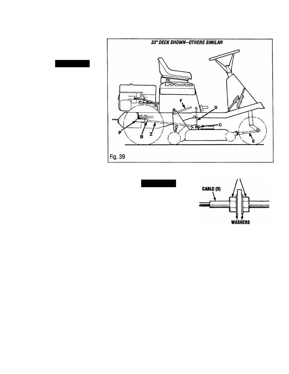
1. Remove belt guide (P, Fig. 39)
2. Move mower iift lever (I, page 16)
downward to set mower in the lowest
position.
3. Remove the belt from the engine pulley
(B). It may be necessary to turn the
differential to remove belt.
4. Remove hitch pins (C) and disconnect
lift rods (D).
5. Remove hitch pins and disconnect
pivot rods (F) from iift piate.
6. Disconnect mower drive cable cable (S,
Figs. 41,42 & 43 on the foiiowing pages)
from spring (FI). Loosen nuts securing
cable to cable support (See Fig. 40).
Remove cable from deck.
7. Remove clevis pin from the front of rod
end (E, Fig. 39), reieasing mower.
8. Slide mower out from under the
tractor. Swing the lift rods (D) forward or
backward to aiiowfor easy removal.
MOWER BELT REPLACEMENT
A\
WARNING!
BEFORE REPLACING THE MOWER
DECK BELT, SHUT THE ENGINE OFF,
MOVE THE MOWER BLADE CLUTCH
LEVER DOWN TO ITS DISENGAGED
POSITION, APPLY THE PARKING
BRAKE, ALLOW THE ENGINE TO COOL,
DISCONNECT THE SPARK PLUG WIRE
AND PREVENT IT FROM TOUCHING
THE SPARK PLUG, AND REMOVE THE
KEY FROM THE KEYSWITCH.
FAILURE TO FOLLOW THIS
INSTRUCTION COULD RESULT IN
PERSONAL INJURY OR PROPERTY
DAMAGE.
28” Mower Drive Belt
Replacement
1. Remove belt guide (P, Fig. 39) and
loosen guides (Y & H, Fig. 41 on following
page).
2. Rotate idler arm (B, Fig. 41) away from
mower sheave and remove oid beit.
NUTS(R)
iq
TI
3. instaii new belt (Z) under belt guide (Y) to engage drive,
on pulley (X).
CABLE SUPPORT(Q)
Fig. 40
4. Re-tighten idler pulley bolt (T). Make
sure guide (Y) is in approximate position
as shown.
5. Assemble belt onto engine sheave and
siide beit guide (P, Fig. 39) as far forward
as possibie. Re-tighten guide (P). NOTE:
It may be necessary to rotate differential to
assemble. Check clearance between guide
(P) and bolt heads on differential. A gap
of 1/8" should exist.
Lift mower blade drive lever (F, page 15)
snnanfi flrivfi.
25