33” decks only, Replace seat, seat support cover and seat switch, Assembly (coni.) – Bolens 13067 User Manual
Page 13: Danger
Attention! The text in this document has been recognized automatically. To view the original document, you can use the "Original mode".
ASSEMBLY (Coni.)
3. To install mower deck, See the
DECK
INSTALLATION on
page 9.
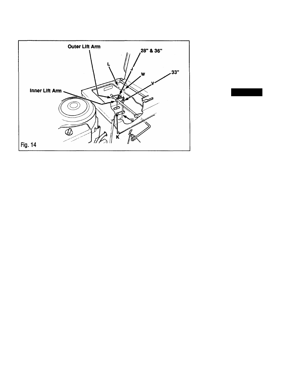
33” Decks Only
1. If swivel (V, Fig. 14) is not attached to
INNER lift arm, remove hair pin and
washer. Attach swivel to the INNER lift
arm. Swivel loop should face to the inside
(right), over the INNER slot. Place washer
and attach hair pin. Hair pin should be on
the outside (left) of lift arm.
2. Slide link (U) upward, through the
INNER slot on the frame. Slide link
through swivel (V). Thread nut (W) onto
link. The position of nut will determine the
height of the mower when set in transport
postions. See instructions in the DECK
ADJUSTMENTS on page 14.
Test Interlock System
Before operating unit, perform the
interlock system test outlined in the
CONTROLS AND OPERATION
on
page 20.
A \
DANGER!
Replace Seat, Seat Support
Cover and Seat Switch
1. Position seat support cover in position
as shown in Fig. 12. Thread 2 screws (C)
into gas tank, but do not tighten. Thread
screws (A) into the sides of seat support
cover. Tighten all hardware.
2. Position seat support on seat support
coverasshowninFig. 12. Secure seat
support with screws (U).
3. Plug in seat switch.
4. Position shift quadrant (Q) as shown.
Secure with screws (B, Fig. 11).
5. Secure shift knob onto end of shift
lever.
6. Lower seat.
THE SAFETY INTERLOCK SWITCH
SHOULD SHUT DOWN THE ENGINE
WITHIN A FEW SECONDS AFTER THE
OPERATOR LEAVES THE SEAT. IF
THIS SWITCH FAILS TO OPERATE,
HAVE THE MOWER SERVICED
IMMEDIATELY BY AN AUTHORIZED
BOLENS® DEALER. SEVERE INJURY
COULD RESULT FROM NOT
FOLLOWING THIS INSTRUCTION.
13