S3 hold these gears in mesh – SINGER 251 User Manual
Page 44
Attention! The text in this document has been recognized automatically. To view the original document, you can use the "Original mode".
44
THE ARM SHAFT (continued)
S3
HOLD THESE GEARS IN MESH
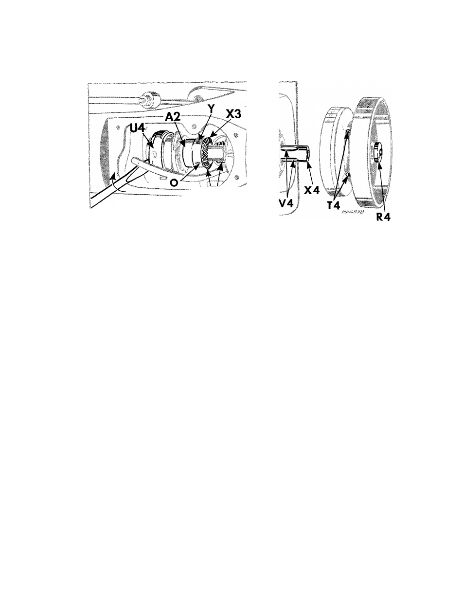
Fig. 70. Replacing the Arm Shaft
REPLACEMENT-
(See Fig. 70)
CAUTION:
Make
certain
that
the
OIL-REMOVING
WICK ASSEMBLY is
out
of the machine.
1.
Insert
the
machine-pulley-end of the
arm shaft
into the arm shaft bushing at the head of the
machine arm.
2.
Make certain that the needle bar crank is turned
to the position shown in
Fig. 69,
clearing the
three wick loops in holder
W4.
3.
While still holding the bevel gears at
S3
in mesh,
with a screwdriver, as shown in
Fig. 70,
push the
arm shaft
X4
straight through the machine arm,
the feed eccentric
U4
and the feed-eccentric-and-
bevel-gear
X3, Fig. 70.
(A light tapping with the
palm of the hand, against the needle bar crank
end, may be required.)
4.
Replace machine pulley so that the two set screws
T4
will locate over the two grooves
V4
on the
shaft and securely tighten set screws
T4.
5.
Replace
and
tighten
the
arm
shaft
screw
R4
sufficiently to remove all end play of the shaft
without binding.
Test the arm shaft for freedom
in rotation.
6.
Move bevel gear
X3 toward machine pulley
and
securely tighten feed timing screw Y.
7.
Place the first finger of one hand on one side of
the arm shaft and the first finger of the other
hand on the other side of the arm shaft so that
both fingers contact the bevel gear (on vertical
shaft)
that
mates
with
the
gear
X3.
Feel
for
slight
backlash.
If
there
is
no
backlash,
loosen
timing screw Y and set screw O. Lightly tap gear
X3 away from mating gear until there is just a
slight
amount
of
backlash.
Then
securely
tighten
timing screw Y and the set screws in gear X3. Re
check the backlash.
8.
Using a screwdriver, as shown in
Fig. 70,
move
feed eccentric
U4
as close as possible to the con
necting rod
A2, Fig. 70
and tighten the timing
screw and two set screws in eccentric
U4.
9.
Check the adjustment and timing of parts dis
turbed and correct where necessary, according to
the instructions on
pages 18
through
25.
10.
Replace the oil-removing wick assembly, as in
structed on
pages 39
and
41.
11.
Replace thread take-up, as instructed on
page
35.
12.
Replace presser bar and presser foot, as in
structed on
page 33.
13.
Replace the upper needle bar bushing and the
needle bar, as instructed on
page 33.
14.
Replace thread take-up oil guard
W2, Fig. 54,
page 36.
15.
Replace arms side shield and wick, as instructed
on
page 36.
16.
Replace the oil lead beneath the arm top cover.
17.
Replace the arm top cover and tighten its four
screws.
1 8. Replace the face plate and tighten its four screws,
as instructed on
page 18.