Slide into recess pull wick – SINGER 251 User Manual
Page 40
Attention! The text in this document has been recognized automatically. To view the original document, you can use the "Original mode".
40
OIL-REMOVING WICK ASSEMBLY (continued)
«
Ip
' ‘
¥§ I
Hi
\
^
‘.i-
®E'-'''5.’ Ji;
‘'X
Bf f
iiii i
SLIDE
INTO
RECESS
PULL
WICK
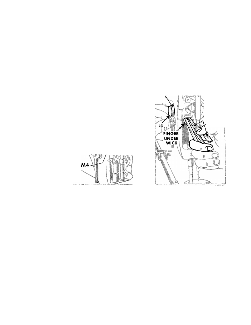
Fig. 63. Replacing Oil-Removing
Wick and Holder in Head of Machine
Fig. 64. Pulling Wick into
Machine
REPLACEMENT-
1.
Turn machine pulley over toward operator until
the needle bar crank is in the position shown at
M4, Fig. 63.
2.
Fold
oil-removing
wick
along
the
side
of
the
holder body, as shown in
Fig. 63
and insert oil-
removimg
wick,
holder
and
hinge
plate
into
head of machine.
3.
Place index fìnger under wick and holder body
and
simultaneously
pull
the
oil-removing
wick,
as required, sliding the hinge plate and cover
L4
fully Into its recess in the head of the machine,
as shown in
Fig. 64.
4.
Securely tighten the four screws
K4, Fig. 63.
5.
Check the entire assembly to make certain that
the holder body
(see 04, Figs 61
and
62)
hinges
freely under the needle bar crank.