Upper timing needle bar at lowest point – SINGER 251 User Manual
Page 18
Attention! The text in this document has been recognized automatically. To view the original document, you can use the "Original mode".
в
1 8
ТО SET THE NEEDLE BAR AT THE CORRECT HEIGHT
нк)!
UPPER
TIMING
NEEDLE BAR
AT
LOWEST POINT
I
м/с 25I-I
.484 inch
M/C25I-2
and 25I-3
.195 inch
UPPER
TIMING
MARK
NEEDLE BAR
vAT LOWEST
POINT
mmms
Fig. 28. Setting Needle Bar Height on Machines with Timing
Marks Aligned with UPPER Needle Bar Bushing
PREPARATION;
Remove face plate, slide plate and throat plate. See
that needle is correctly set in needle bar, as instructed
on
page 8.
NOTE:
FOR MACHINES ON WHICH TIMING MARKS SHOULD
ALIGN WITH UPPER NEEDLE BAR BUSHING-
Top of bushing
A, Fig. 28
must be flush with top of
casting, as shown in
Fig. 28.
To reset bushing, loosen
screw
В
and raise or lower bushing, as required.
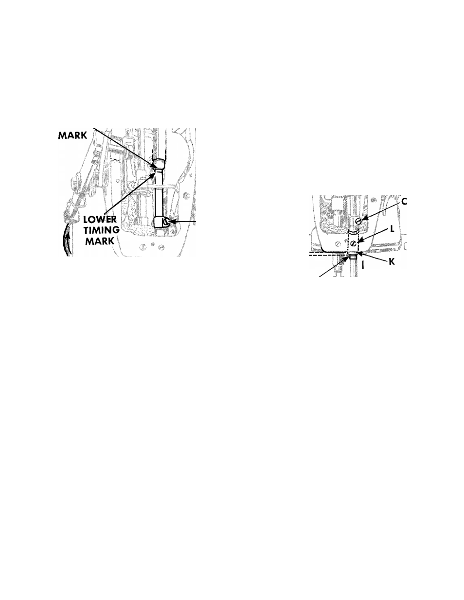
FOR MACHINES ON WHICH TIMING MARKS SHOULD
ALIGN WITH LOWER NEEDLE BAR BUSHING-
Lower end of bushing
K, Fig. 29
must be set as
shown in
Fig. 29.
To reset bushing, loosen screw
L.
Fig. 29. Setting Needle Bar Height on Machines with Timing
Marks Aligned with LOWER Needle Bar Bushing
CHECK;
When needle bar is at its lowest point (during rota
tion
of
machine
pulley),
UPPER TIMING MARK
on
needle bar should be level with lower end of bushing.
Check timing of hook as instructed on
page 21.
SETTING:
Loosen clamping screw
C, Figs. 28
and
29.
Raise or
lower needle bar so that UPPER TIMING MARK is level
with
lower
end
of
bushing.
Then
securely
tighten
screw
C.
Replace throat plate and slide plate.
When
replacing
the
face
plate,
make
certain
that
the screw holes in the face plate gasket are aligned
with
the
respective
screw
holes
in
the
face
plate;
avoiding
injury
to
the
gasket
and
consequent
oil
leakage.