The oil pump – SINGER 251 User Manual
Page 31
Attention! The text in this document has been recognized automatically. To view the original document, you can use the "Original mode".
31
THE OIL PUMP
TO REMOVE
1.
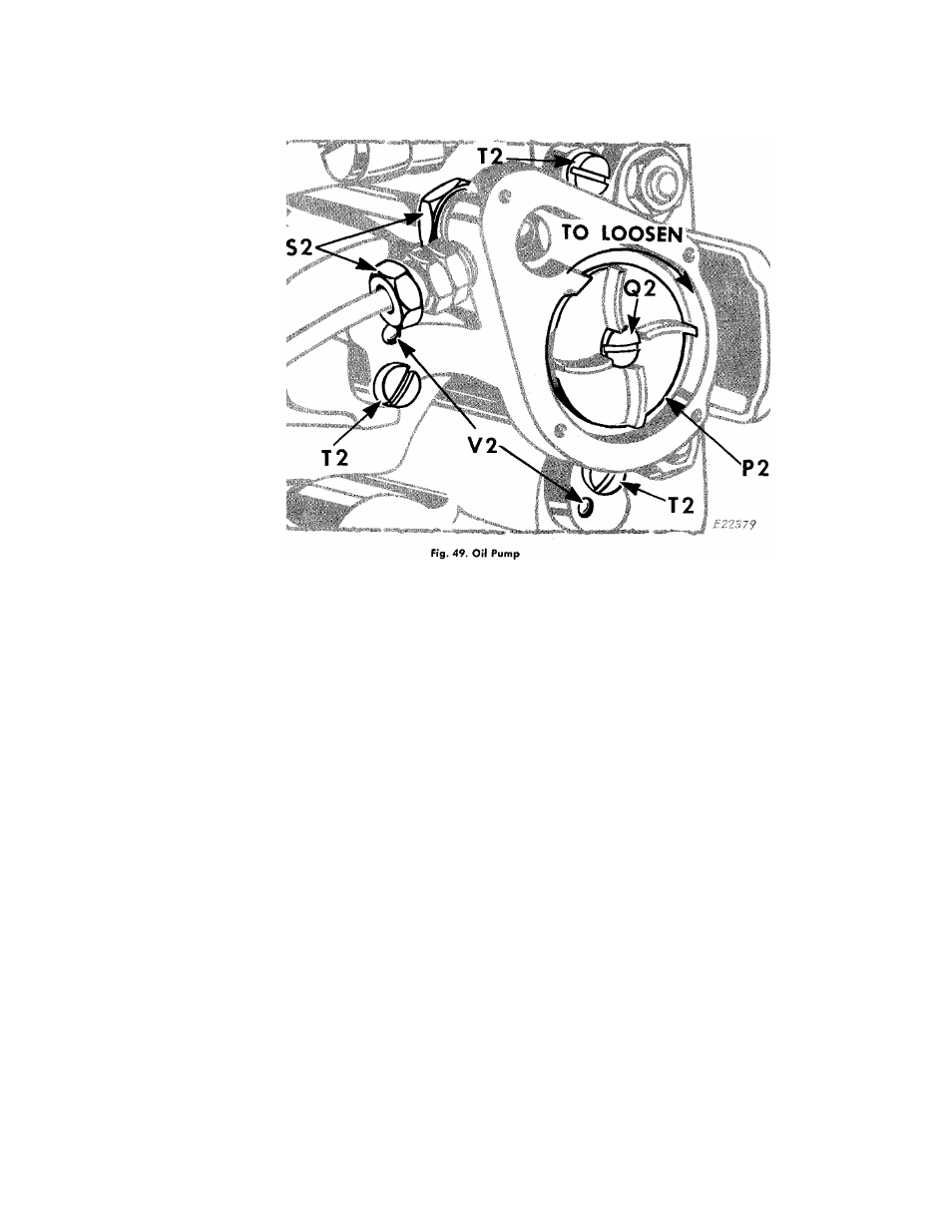
Loosen the two oil pipe clamping sleeve nuts 52,
Fig. 49.
2.
Remove the four screws
N2, Fig. 48.
3.
Remove the screen frame, screen and oil pump
cover
02, Fig. 48.
4.
Remove the locking screw
02, Fig. 49.
5.
Remove the impeller P2, by
turning it over toward
the RIGHT (clockwise)
to loosen it, as instructed
in
Fig. 49.
CAUTION:—
The impeller
P2
is designed to be screwed
to the shaft by means of a
LEFT-HAND THREAD
and
must be
turned over toward the right to be loosened.
Avoid damage to this impeller, as the efficient auto
matic lubrication of the machine is dependent upon it.
6.
Remove the three screws T2.
TO REPLACE
1.
Place
oil
pump
body
on
underside
of
ma
chine
bed,
so
that
position
pins
V2,
slip
into
proper holes in machine casting, as shown above.
2.
Replace and securely tighten the three screws
T2.
Make certain that machine turns freely as screws
are tightened.
3.
Carefully
replace
impeller
P2, turning it over
toward the LEFT
to screw it on arm shaft (see
CAUTION at left).
4.
Make certain that impeller
P2
is not so tight that
it will bind arm shaft. Make certain also that im
peller clears both top and bottom of interior of
oil pump body, then lock it in position by means
of locking screw
Q2.
5.
Replace pump cover, screen and frame
02
and
four
screws
N2,
Fig.
48.
Securely
tighten
screws
N2.
7.
Carefully pull the oil pump body off the lower
end of the upright arm shaft.
6.
Replace two oil pipes in oil pump body, as shown
above, and securely tighten sleeve nuts 52.