Z 4 x 4 – SINGER 251 User Manual
Page 43
Attention! The text in this document has been recognized automatically. To view the original document, you can use the "Original mode".
43
THE ARM SHAFT (continued)
Z 4
X 4
i
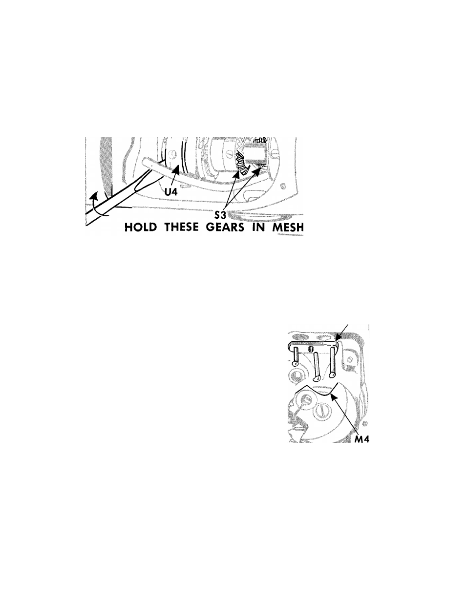
Fig. 68. Removing the Arm Shaft
REMOVAL (Continued)
CAUTION:
The
feed-timing-bevel-gears
at
S3,
Fig. 68
have been lapped together at the factory and
should
be kept in mesh
(as instructed in
Fig. 68)
throughout
the removal and replacement of the arm shaft.
14.
While maintaining needle bar crank
M4
at posi
tion shown in
Fig. 69,
hold these gears in mesh
by holding the blade of a large screwdriver be
tween the arm casting and the feed eccentric
U4,
as shown in
Fig. 68;
then push the end of the
arm shaft
X4, Fig. 67
through the bushing
Z4,
Fig. 67.
15.
Using another shaft (or a drift pin of the same
diameter
as
the
arm
shaft
on
these
machines),
push the arm shaft
X4
further through the ma
chine
(still
keeping
the
gears
at
S3
in
mesh).
This
temporary
shaft
must
be
pushed
sufficiently
far into the machine to
hold the entire gear and
feed eccentric mechanism in position
upon it until
the new arm shaft is installed.
W4
Fig. 69. Position of Needle Bor
Crank, During Removal of Shaft
16.
Finally
grasp
the
needle-bar-crank-end
of
the
arm shaft firmly at the face plate end and pull
the arm shaft straight out of the machine.