SINGER 251 User Manual
Page 41
Attention! The text in this document has been recognized automatically. To view the original document, you can use the "Original mode".
41
OIL-REMOVING WICK ASSEMBLY (continued)
if
Ml
m
III
I
IB
il
'smi
1
.«w»« J
'
N-
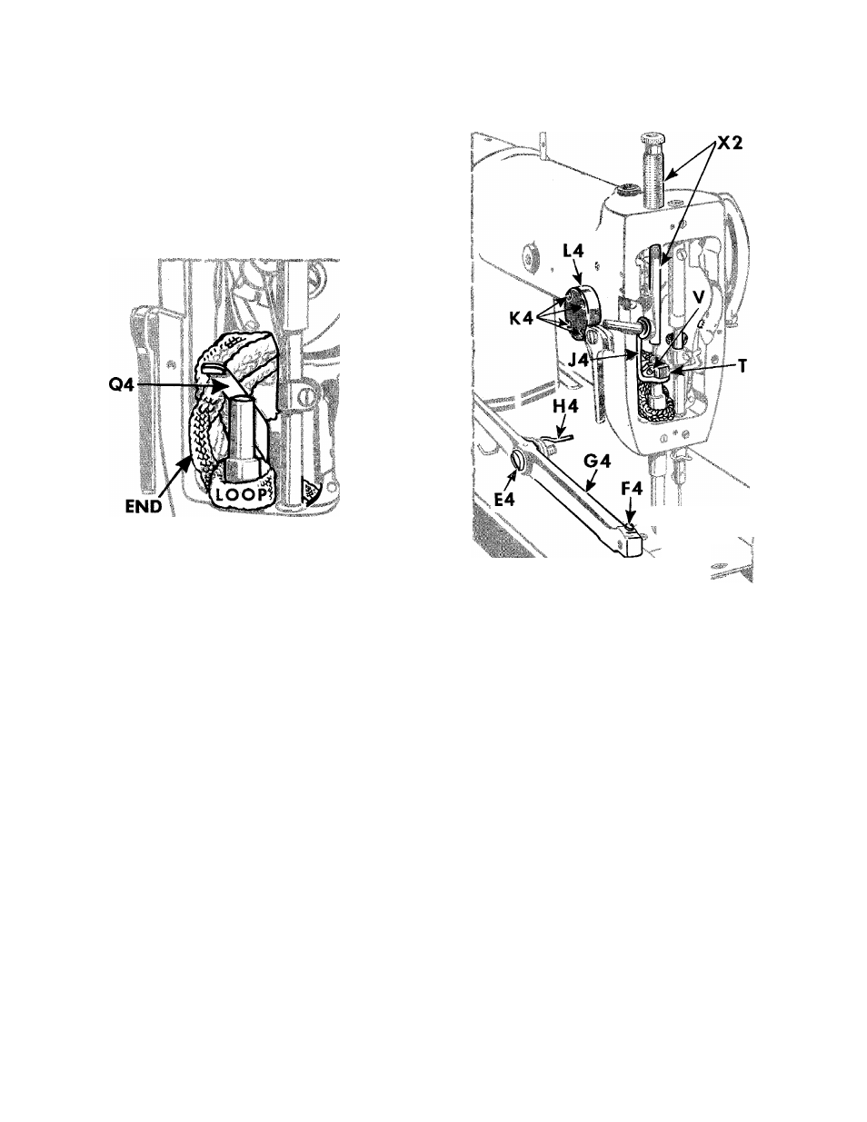
Fig. 65. Location of Wick
Loop and Wick End
in Machine Head
Fig. 66. Replacement of Other
Parts in Head of Machine
LOCATION OF WICKS-
1.
Replace
END
of
wick
behind
tension
releasing
lever
Q4
and into oil pool behind lower needle
bar bushing, os shown in
Fig. 65.
2.
Replace LOOP behind and then under tension re
leasing lever
Q4
and out over lower presser bar
bushing, as shown in
Fig. 65.
REPLACEMENT OF OTHER PARTS
1.
Replace presser bar lifting link
J4, Fig. 66
with
stud.
2.
Replace guide bracket
T, Fig. 66. (See page 33,
also.)
Tighten screw
V, Fig. 66.
3.
Replace arm side shield with wick, as instructed
on page 36.
4.
Replace upper half of presser bar and presser
bar thumb screw
X2, Fig. 66.
5.
Replace presser foot and presser foot screw.
6.
Place presser foot lifting lever
G4, Fig. 66
with
spring
H4
on machine arm and fasten lever to
arm with hinge screw stud
E4, Fig. 66.
7.
Tighten screw
F4, Fig. 58.
8.
Replace face plate as instructed on page 18.