Sears 917.25591 User Manual
Page 9
Attention! The text in this document has been recognized automatically. To view the original document, you can use the "Original mode".
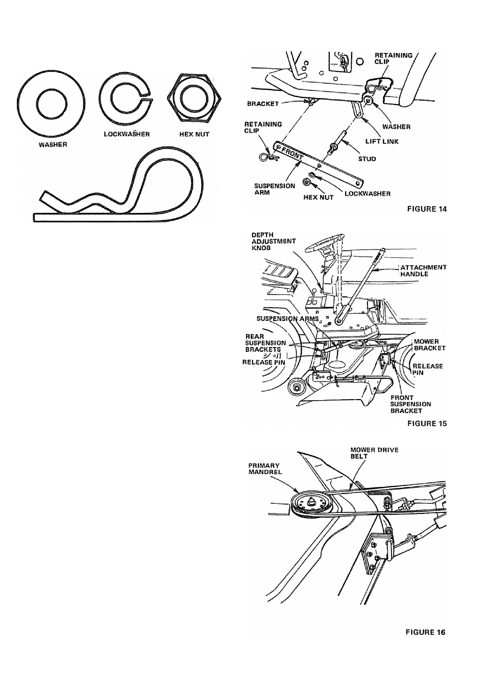
4, The Mower Suspension Arms and Fasteners {shown full
size below) are found in Bag of Parts,
RETAINING CLIP
5. The Mower Suspension Arms have "FRONT" stamped
between hoiss. Place the Suspension Arms on Brackets on
both sides of Frame. Retain with Retaining Clip (Fig. 14).
6. Slide Mower under Tractor, Deflector to right harid side.
7. Siide Front Suspension Brackets Into Mower Brackets, Re
tain with Release Pins (Fig. 15), Turn Depth Adjustment
Knob counterclockwise until it stops.
8. Siide Suspension Arms into Rear Suspension Brackets,
Retain with Release Pins (Fig, IS),
9. Turn Depth Adjustment Knob (Fig. 15) clockwise (z''™^)
to remove slack from Mower Suspension. Raise Attaciiment
Handle to full up position,
10, Press plunger down and push Attachment Handle forward
to lower mower to ground. Roll Drive Belt over Primary
Mandrel (Fig. 16).
-9