Sfohaoe, Atmchme^t lift adjostmew, Msimucimms – Sears 917.25591 User Manual
Page 16: Tractor maimtewawce
Attention! The text in this document has been recognized automatically. To view the original document, you can use the "Original mode".
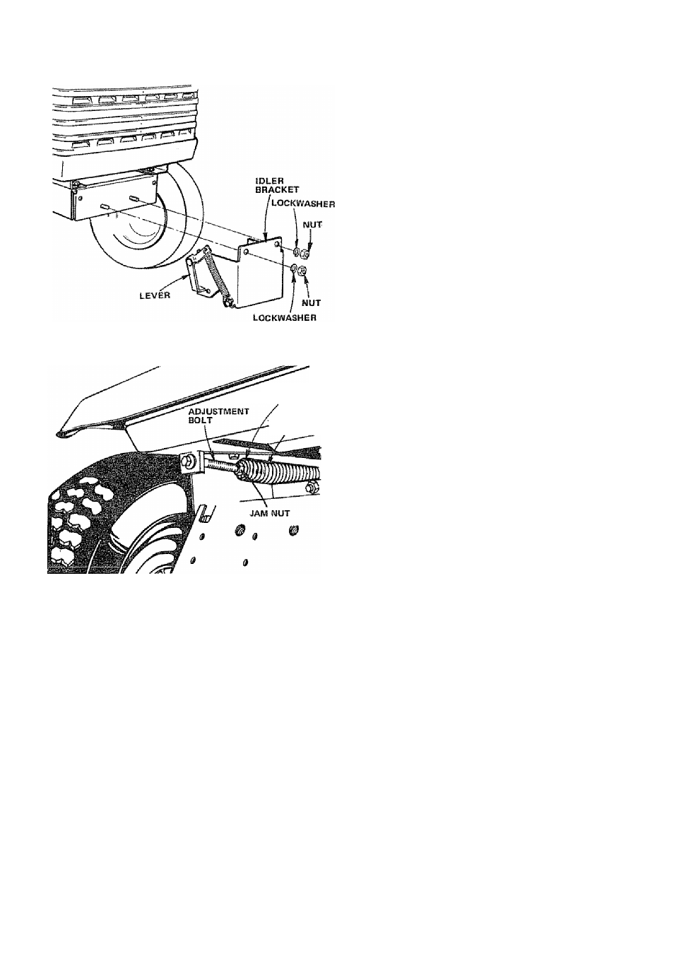
FIGURE 32
NOTE: WHEN OPERATING TRACTOR WITHOUT MOWER;
REMOVE IDLER BRACKET FROM FRONT OF TRACTOR*
1. Puli Belt up through Idler Bracket and out of tractotu Usé
Lever to swing Tension Pulley for Belt removal.
2. Remove Lockwashers artd Nuts from Idler Bracket (Fig,
32).
SfOHAOE
Remove mower from tractor for winter storage. When mower
is to be stored for a period of time, dean it thoroughly, re
move ail dirt, grease, leaves, etc. Give blades and underside of
housing a good coat of grease or rust preventative. Store in a
dean dry area.
Each outer mandrel should be greased thru the Grease Fitting
located between mower blade and underside of the mower
housing (Fig, 28). Give each Grease Fitting 6 shots of Grease.
Wipe fitting clean before greasing. Use high performance ex
treme pressure lubricating grease. (Amdex No. 1 EPor equiva*
lent), Wipe mandrel dean of excess grease. This grease may be
obtained by ordering thru your nearest Sears Repair Parts 0e»
partmenL Part No. 2B57R.
SPRIWe
BUSHING
ATTACHMENT
LIFT SPRING
FIGURE 33
ATmCHME^T LIFT ADJOSTMEW
Due to different weights of Attachments, the Attachment
Lift Spring may require adjustment, the Adjustment Bolt
is located on rear of tractor top left side (Fig. 33).
1, Holding Spring Bushing with Wrench, loosen Jam Nut
2. Turn Adjustment Bolt clockwise ( /^) to extend Spring
and reduce lift effort (for heavier Attachments).
3, Turn Adjustmertt Bolt counterclockwise (P^) (for lighter
Attachments),
4. Retighten Jam Nut against Spring Bushing,
NOTE: DO NOT ADJUST FOR MAXIMUM SPRING TEN
SION WHEN USING LIGHT ATTACHMENTS SUCH AS A
MOWER. ADJUST LIFT SPRING TO AID IN LIFTING
ATTACHMENT - DON*T OVER POWER SPRING. WHEN
REMOVING
ATTACHMENT
ALWAYS
ADJUST
WITH
SPRING TENSION TO ITS LOWEST POSITION.
DISCHARGING
CHARGING
J-
T
о
15
DC AMPERES
□
a
LJ
Q
10
В
0
5
10
C3
15
AMMETER
FIGURE 34
TRACTOR MAIMTEWAWCE
msimucimms
To keep your tractor running better, longer; perform nec
essary service using the following Maintenance Schedule.
Each time you start your tractor, check your Ammeter (Fig.
34). The needle should move towards the + (charging) mark
indicating the battery is being charged as you operate the trac
tor. The headtights will not show a discharge on the ammeter
because they are not connected to the battery (they have their
own eiectrical source, see page 26). If you have з lift motor
connected it will show a discharge when being operated.
A
DISCONNECT SPARK PLUG WIRES TO
PREVENT ACCIDENTAL STARTING BE
FORE MAKING ANY INSPECTION, AD
JUSTMENT OR REPAIR (EXCEPT CAR
BURETOR)
-16-