Imitg^l sepmice, Sfahtliyg the eweiwe – Sears 917.25591 User Manual
Page 6
Attention! The text in this document has been recognized automatically. To view the original document, you can use the "Original mode".
GSAR SHIFT
CONTRQI. LEVER
FIGURE 9
IMITg^L SEPMiCE
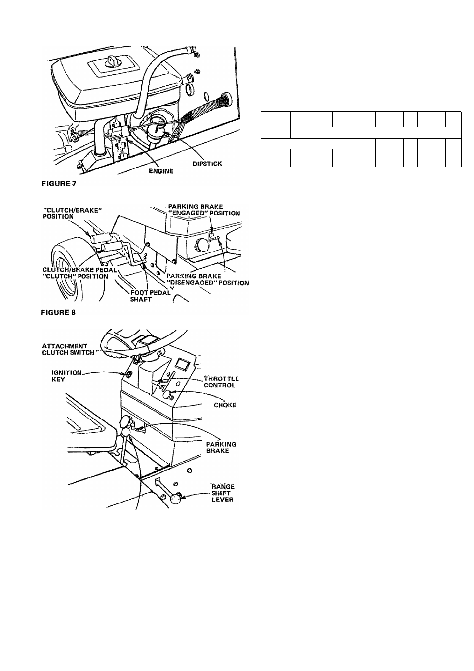
1. This engine hai been shipped filled with oil. Check Engine
Oil Level with Tractor on level ground. Wipe Dipstick
(Fig. 7) clean, push it in tight for a few seconds, remove
and read Oil Level. If necessary, add Oil until ’'FULL*'
mark is reached.
RiCOMMEWDED SAE VISCOSITY GRADES
30 OR 10W-30
y
^ 5W-2SOR5W-30
-20®
0®
32®
60®
80®
100°
TEMPERATURE RANGE EXPECTED gEFORE NEXT OIL
CHANGE. ALL OILS MUST MEET A.P.I. SERVICE CLAS
SIFICATION SD, SE, OR SF.
Capacity Is 3 pints, NOTE; DO NOT OVERFILL. Dipstick
assembly must be securely tightened into tube at all times
when engine is operating.
2, Fill Fuel Tank (Fig. 6). Use fresh, clean, unleaded auto
motive gasoline. (Leaded "Regular" grade gasoline is an
acceptable substitute, but will increase carbon and lead
oxide deposits and reduce valve ilfej. Capacity is 3 - 1/2
gallons.
WARNING: DO NOT USE GASOHOL OR METHANOL.
These type fuels react with water content in the fuel
and tend to form strong acids which can corrode metal
parts and harm rubber and plastics.
FILL TO BOTTOM OF GAS TANK FILL
ER NECK. DO NOT OVERFILL. WIPE
OFF ANY SPILLED OIL OR FUEL. DO
NOT STORE, SPILL OR USE GASOLINE
NEAR AN OPEN FLAME.
3, Reduce Tire pressure to 14 PSI in front and 10 PSl in rear
Tires. (Tires were overinflaied for shipping purposes},
4. Remove bands from Mower Suspension Bracket (Fig. 11).
SfAHTliyG THE EWeiWE
A
LEARN TO START, STOP AND REVERSE
YOUR TRACTOR IN A LARGE, OPEN
AREA.
NOTE: THIS TRACTOR JS EQUIPPED WITH INTERLOCK
SWITCHES TO PREVENT STARTING OF THE TRACTOR
ENGINE WHILE THE ATTACHMENT CLUTCH OR THE
TRACTOR CLUTCH IS ENGAGED,
A
IMMEDIATELY
REPLACE
SWITCHES
THAT ARE NOT IN PROPER WORKING
ORDER. DO NOT ATTEMPT TO DEFEAT
THE PURPOSE OF THESE SWITCHES.
■6
1. Place Attachment Clutch Switch in "DISENGAGED"
position (Fig. 9).
2. Push Clutch-Brake Pedal fully into brake position (Fig. 8),
3. Place Gear Shift Control Lever in "N" neutral, start posi
tion and Range Shift Lever in "
n
" lieutral position (Fig. 9).