R.h. side of tractor – Sears 917.25591 User Manual
Page 22
Attention! The text in this document has been recognized automatically. To view the original document, you can use the "Original mode".
GOVERNOR
CONTROL
" "s
HOLE "A
FIGURE 50
R.H. SIDE OF TRACTOR
ENGINE
PULLEY
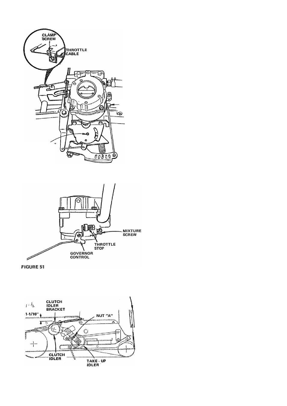
CARBURETOR ADJUSTMENT
Never attempt to change maximyrn engine speed. This is
preset at the factory and should only be changed by a quali
fied service technician who has the necessary equipment.
a. Move Throttle Control (on the dashboard) to ‘SLOW*
position. Remove'Air Cleaner {Fig. 36).
b. Check that two holes "
a
" lirre up. If not, loosen Clamp
Screw and adjust Throttle Cable until the two holes do
line up {Fig, SO • inset),
A
REFER TO
PAGE 8.
'STARTING THE ENGINE",
c. Start Engine and allow to warm for five minutes. Make
final adjustments with engine running.
d. High Speed is fixed, no adjustment is possible.
e. Adjust Carburetor Mixture Screw to suggested initial
setting.
- Turn Mixture Screw clockwise (r^) closing finger
tight ONLY, and then turn counterclockwise (
)
1-1/2 turns (Fig. 51). CAUTION: VALVE MAY
BE DAMAGED IF TURNED IN TOO FAR.
f. Hold Governor Control against Throttle Stop. Turn
Mixture Screw clockwise {
) urstil engine begins to
run rough (Fig. 51).
g. Turn Mixture Screw counterclockwise (F“^) until engine
begins to run rough. Set Mixture at smoothest idle
between the two points attairred in steps f and g,
h. Release Governor Control. Engine will speed up for
goverrsed idle. Replace Air Cleaner.
V BELT ADJUSTMENT
A new V-Beit may stretch after the first few hours of opera
tion resulting irr loss of ground speed.
a. To tighten Belt, remove (4) Hex Washer Head Tapping
Screws from Shift Cover Plate (Fig. 48) located on top
of tractor frame. Remove the Cover Plate,
b. Place Parking Brake Lever In '^ENGAGED" position.
Refer to "Stopping Your Tractor, page 7,
Loosen Nut located on outside of R.H, Chassis
Frame (Fig, 56), slide Take-Up Idler down approximate
ly 1/2" and tighten Nut "
a
".
Disengage Parking Brake,
Check position of Clutch Idler Bracket (Fip, 52).
Repeat steps b thru e until a 1 - 1/16’ dimension is
obtained between Idler Tab and Frame as shown in Fig
S2,
Tighten Nut "A" securely.
Reinstall Shift Cover Plate and (4) Screws removed in
step a.
c.
figure
S2i
-22