Siieided – Sears 917.25591 User Manual
Page 21
Attention! The text in this document has been recognized automatically. To view the original document, you can use the "Original mode".
^SiiEiDED
1, Make sure all nuts on bolts are tight and cotter pins are se
cure. ObservfB ail safety precautions. Keep Tractor weli
lubricated (refer to page !8}.
2 yQE.,(y
adjustment
If any parts in Front Axle or Steering Mechanism are being
replaced, Toe-In adjustment is required,
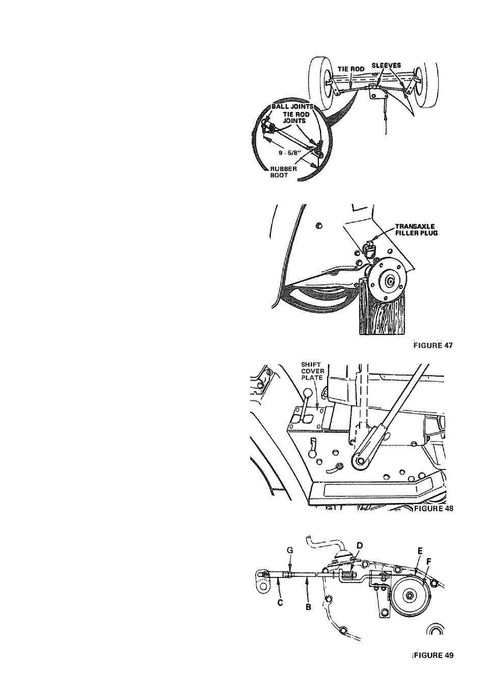
a. Loosen Jam Nuts (Fig, 46j at each end of Tie Rod
Adjustment Sleeves.
b„ Adjust both Tie Rods so that Tie Rod Joints measure
9- 5/8 ' from center to center.
c. On front of frorrt tires measure distance from center to
center {measurement No,lK
d. On rear of front tires measure distance from center to
center {measurement No. 2).
e. Compare measurements - measurement No. j should be
1/8- 1/4 (ess than measurement No. 2,
f. If not adjust each Tie Rod equally to get correct meas
urement
g. Tighten Jam^ Nuts making sure Tie Rod Joints are
parallel {180“) to each other. TTils adjustment secures
proper front wheel Toe-In and Steering operation.
3. CHECK TRANSAXLE OIL LEVEL
a. Remove Filler Plug {Fig. 47) from Transaxie. Oil Level
should be even with Filler Plug threads. Add S.A.E, 30
Motor Oil if necessary,
b- Check Pressure Relief Valve (Fig, 45 • Inset) located on
R.H. side near top. it should spring completely closed
when pulled out by hand and released.
4. BRAKE ADJUSTMENT
TIE ROD _______ ,
ADÄiSTMEWT^ \
A
IF TRACTOR REQUIRES MORE THAN
SIX
FEET
STOPPING
DISTANCE
IN
HIGHEST
GEAR
ON
A
LEVEL
DRY
CONCRETE OR PAVED SURFACE THEM
BRAKE MUST BE ADJUSTED,
a. Remove (4) Hex Washer Head Tapping Screws from
Shift Cover Plate (Fig. 48), located on top of tractor
frame. Remove the Cover Plate.
b. Loosen Jam Nut (G) on Brake Rod (B) at Clevis (.C)
(Fig. 49). If you find it difficult to loosen Jam Nut (G),
remove Cover Plate in L,H. Frame Rail,
c.
Rotate Brake Rod (B) counterclockwise, (/^) turning
Brake Rod out of Clevis (C) four to six turns.
d. Start tractor with Transmission in "NEUTRAL" posi
tion
Depress Brake-Clutch Pedal to the point where Beit
stops moving. Hold Brake-Clutch Pedal in positiorr by
engaging Parking Brake If Belt begins to move after en
gaging Parking Brake, depress Brake-Clutch Pedal to next
notch on Parking Brake.
Shut engine oft. Rotate Brake Rod (B) clockwise by
hand, turning Brake Rod into Clevis (C), until tight,,
Tighten Jam Nut (G) on Brake Rod (B) at Clevis (Gl
(Fig. 49).
Reinstall Lift Cover Plate and four {4) Mounting Screws,
If Cover Plate was removed in step b it should be re
placed.
e.
f.
JAM NUTS
STEERtNQ LINK
FIGURE 46
21