Sears 917.25591 User Manual
Page 23
Attention! The text in this document has been recognized automatically. To view the original document, you can use the "Original mode".
b,
c,
d,
e
t.
g.
7. V BELT REPLACEIV1ENT
BELT REMOVAL
The belt on this tractor is special for this application.
Always replace with the Sears belt number in the parts
list. It is not necessary to remove mower,
a, Raise hood and disconrrect negative ground battery
cable.
Set parking brake |to get belt slack).
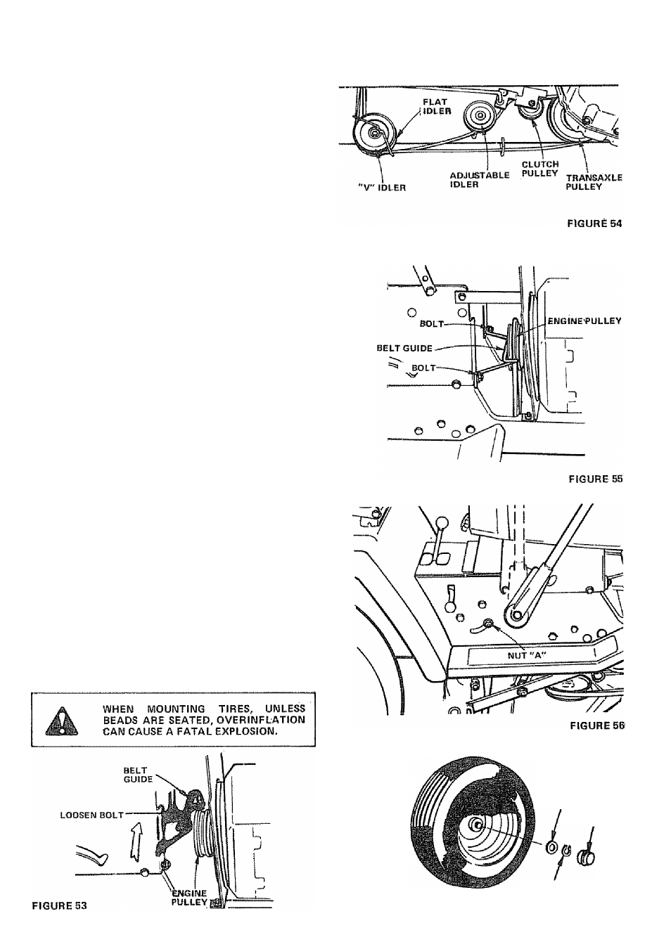
Loosen (do not remove) two Engine Pulley Belt Guide
Bolts and swivel R.H. side of Belt Guide up. Tighten
L.H. Boit to hold Belt Guide in position (Fig, 53).
Roll Belt off Engine Pulley,
Roll Belt off
Idler, Flat Idler and Adjustable
Idler Pulleys (F}g. B4).
Pull Belt oft Clutch Pulley - between Pulley and Frame,
Pull Belt off Jransaxle Pulley.
Loosen Nut "
a
" on R.H, outside of Frame (Fig, 56).
BELT INSTALLATION
NOTE: THERE IS A BELT iNSTALLATION DECAL
UNDER LEFT HAND FOOTREST.
a. Push Balt down from Engine Pulley area. Place back
(flat) side of Belt on Flat Idler, (Flat Idler is next to
Frame.)
b. Place Belt on Adjustable idler and over Clutch Pulley,
(narrow) part of Beit should engap Clutch Pulley.
c. Place Belt around Transaxle Pulley. ^V" part of Belt
should engage Transaxle Pulley.
d. Make sure v'* part of Belt engages "v" Idler (Fig. 54).
e. Roll Belt over Engine Pulley.
f.
Loosen L.H. Engine Pulley Belt Guide Bolt and swivel
Belt Guide onto R.H. Bolt. Tighten L.H. and R.H. Bolts
securely (Fig, 55),
g. Release Parking Brake. NOTE; WHEN A NEW SELT
HAS BEEN INSTALLED, YOU MUST CHECK V-8ELT
ADJUSTMENT AND BRAKE ADJUSTMENT.
in front at 14 PSI and rear tires
C. I fU FI
a. Maintain tire pressure
at 10 PSI.
b. Keep tires free of gasoline, oil, or insect control chemi»
cals which can destroy rubber.
c. Avoid stumps, stones, deep ruts and other hazards that
may cause tire damage,
d. Removing front wheel for tire repair (Fig, 57),
— Block up front axle securely.
Remove Hub Cap, Klip Ring and Washer to allow
wheel removal.
“ Repair tire artd reassemble. Replace Washer and snap
Klip Ring securely in axle groove. Replace Hub Cap.
e. Removing rear wheel for tire repair.
™ Block up rear axle securely.
— Remove Hub Cap and (5) Hub Bolts to allow wheal
removal.
Repair tire and reassemble. Replace and tighten Hub
Bolts and Hub Cap securely.
WASHER
HUB
CAP
KLIP RING
-23
FIGURE 57