Assembly and alignment – Sears 113.19771 User Manual
Page 17
Attention! The text in this document has been recognized automatically. To view the original document, you can use the "Original mode".
assembly and alignment
3.
Tci correct "heel" condition pioceed as follows:
a.
Rernove left hand carriage cover.
b.
Loosen the yoke clamp handle.
c.
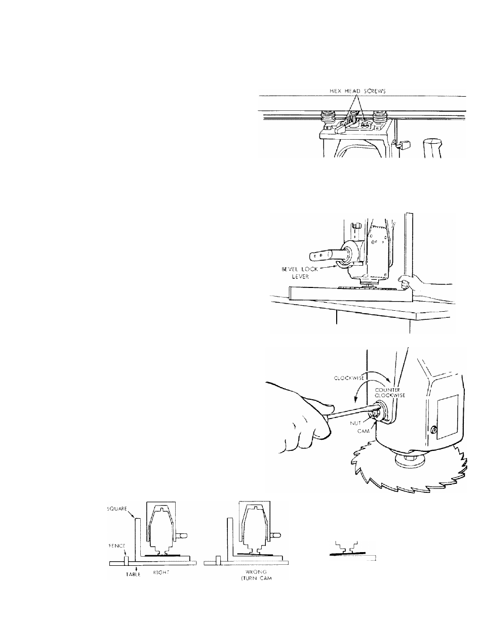
Loosen (slightly) the two hex-head screws.
d- Rotate the yoke assembly until gap between the
saw blade and square is eliminated.
e.
Lock yoke clamp handle and retightcn the two
hex-head screws.
f.
Recheck for "heel" and install carriage cover.
g.
Loosen carriage lock knob.
NOTE.:
This
alignment
procedure
will
simultaneously
set
both yoke indexing positiorrs for blade in and out rip.
LfcFT SIDE OF CARRIAGE
VERTICAL HEEL ADJUSTMENT
1.
With sawblade in 90° cutoff position, elevate saw and
rotate motor to vertical position (Blade Horizontal) and
cf’eck for heel. Make sure bevel lock lever is locked.
2.
Position
square
perpendicular
to
fence
and
between
blade and table, as shown lower arm. Do not allow the
sc]uare to rest against a "set-out" tooth, it must rest flat
ariainsT the blade side.
3.
Ii the saw blade is parallel with tfie table top (no visible
g.tp appears betw'een the saw blade and square), no
adjustment is required.
4.
If there is a visible gap between saw blade and square, a
bevel heel condition exists and adjustment is required.
a.
To correct, unlock bevel lock lever, loosen the rear
motor mount 3/8-16 nut until you can rotate Cam,
and then rotate Cam as shown until gap between
saw blade and square is elirninated.
b. Tighten nut and bevel lock lever and recheck.
c.
Reposition motor in crosscut position.
r\
ZD
:OUNTtRCLOCKWI5[)
17
y/RONG
(TURN CAM
CLOCKWISE)