O 3/4 – Sears 831.159341 User Manual
Page 6
Attention! The text in this document has been recognized automatically. To view the original document, you can use the "Original mode".
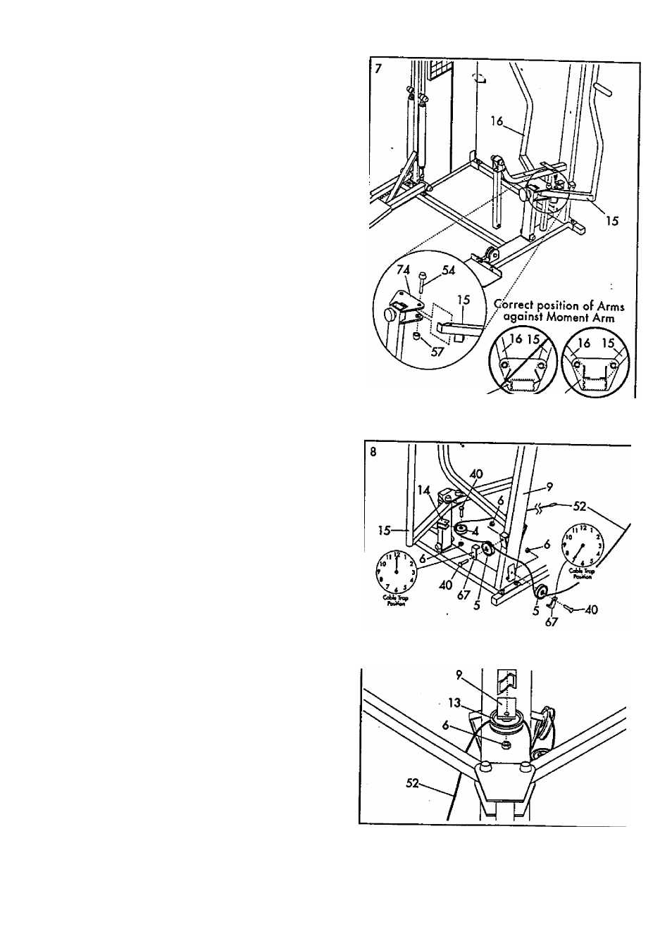
7.
Insert ihe lower end of the Left Arm (15) Info the left
side of the Moment Arm (74). Make sore that the
bracket on the end of the Left Ann Is posifioned as
shown in the inset drawing. If the brocket is not
positioned as shown, the Left Arm will not function
properly.
Tap
a
3/4' Plastic Cap (57) onto one of the ends of
o 3/4
X
4* Axle (54). Align the hole in the end of
the Left Aim (15) with the holes In the Moment Arm
(74). Insert the Axle into the Moment Arm ond the
Left Arm. Top a 3/4" Plastic Cap onto the Axle.
Note: An extra 3/4' Plastic Cap (57) hos been
included with the hardware pack. If you accidental
ly damoge one of the Caps during assembly, use
this extra Cop. Otherwise, the extra Cop may be
discarded.
Attach the Right Arm (16) in the same
manner.
74'
----------. 74
INCORREa CORREQ
8.
Wrap the Weight Cable (52) under a 3 1 /2' Pulley
(5). Attach the Pulley ond a Coble Trap (67) to the
back of the Upright (9) with
a
3/8' x 1 3/4' Bolt
(40) and 3/8' Nylock Nut (6). Make sure thot the
Cable Trop is in the '7 o^clock* position.
Loy the Weight Coble (52) over a 3 1 /2* Pulley (5).
Attoch a CaWe Trap (67) and the Pulley to the left
side of the Upright (9) with a 3/8' x 1 3/4' Bolt
(40) and 3/8' Nylock Nut (6). Moke sure that the
Cable Trop is in the '12 o'clock' position.
Wrap the Weight Coble (52) around a 2' Pulley (4).
Attach the Pulley to tfie Left Arm (15) with a 3/8' x
1 3/4' Bolt (40) and 3/8' Nylock Nut (6).
9.
Wrop the Weight Coble (52) around
a 2
3/4'
Pulley (13). Attach the Pulley to the ir>dicated bracket
on the Upright (9) with a 3/8' x 1 3/4' Bolt (40)
and 3/8'i^k Nut (6).
f—---------- ^