Carrier 48MA User Manual
Page 6
Attention! The text in this document has been recognized automatically. To view the original document, you can use the "Original mode".
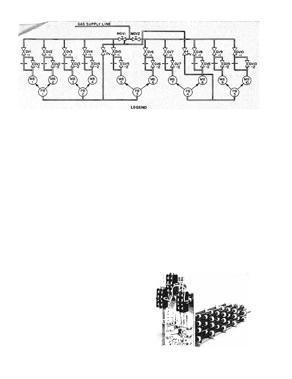
GV
- Gas Vaive (Zone Module)
MS ~ Main Burner
MGV
-
PS -
Main Gas Vaive
Pilot Sorrier
PV
~ Pilot Valve (shutoff;
MOTSS:
t
Pirst stage of gas valve is a 115-vott sok-noid; second stage is a
24-voit soienoid with .60% gas bvpess.
Gnits 48MA034 ano 040 fi ave one pilot shotoff valve feeding all
pilot burners.
Unit is eouipped with a forced-draft blower and: the foiiowing
safety devices: forced-draft airfiow switcfi, tiame rcll-oot pro
tection switch, combustion dtarnbet access door switch, heating
lirrtt switches, and soark-ignitecl automatic pilots. Al! of these
switches are iccateci in the heating section and rrtust. be in safe
condition before tfie inain burners can ignite.
Fig. 3 — Gas Piping Schematic (10-Zone 48MA Unit Shown, 8- and 12-Zone Units Similar)
6. Heating limit switches.
7. Flame rollout protection switch.
In special applications where natural gas supply
is limited, units must be modified to operate under
derated input/output conditions. The 48MA modu
lar multizones can be derated by changing the zone
module burner spuds and gas valve orifices as
follows:
NATURAL GAS FIRED UNITS
T O T A L M O D U L E
D E R A T E D I N P U T ( % )
H i g h F i r e / L o w F i r e
90/45
80/40
70/35
S P U D S I Z E
No 36
No 38
No 41
No 43
G A S V A L V E
O R I F I C E S I Z E
No 36
No. 38
No. 41
No 43
Under these conditions, the units still have 2 stages
of derated heat input. Derating below these limits
is not approved. If single-stage heat is acceptable,
disconnect high fire stage to permit each module
low fire input only (% as shown under low fire).
Contact Carrier Service Department before de
rating to the above limits.
ELECTRIC HEATING SYSTEM (SOME) - The
SOME electric heating system contains single-phase
Nichrome wire coils (see Fig. 4), wired and phase
balanced to provide 2 or 3 steps of heat control.
Each zone has 2 or 3 steps of strip heat available,
controlled simultaneously by the zone thermostat
and the outdoor air thermostat. When heat is
required, the first stage of zone thermostat ener
gizes the first step of zone heating. The second step
(on 3-step units) of heating is controlled by the
second stage of the zone thermostat. The second
(on 2-stage units) and third step of heating is
controlled by the outside air thermostat (OAT.)
and operates simultaneously with the second stage
of the thermostat (on 3-stage units) when the
outside air temperatures are below OAT. setpoint.
The setpoint on the outside air thermostat is
adjustable from 0 to 55 F.
Safety features include:
1. UL certification on entire unit, as well as
electric heat section
2. Manual reset circuit breakers
3. Klixon high-temperature protection
4. Airflow safety for indoor fan motor
5. Fusible links in each heater phase
6. Two-pole contactors on each element
Fig. 4 — Electric Heating Unit (50ME)