Fig. 14 — economizer condensing schematic – Carrier 48MA User Manual
Page 13
Attention! The text in this document has been recognized automatically. To view the original document, you can use the "Original mode".
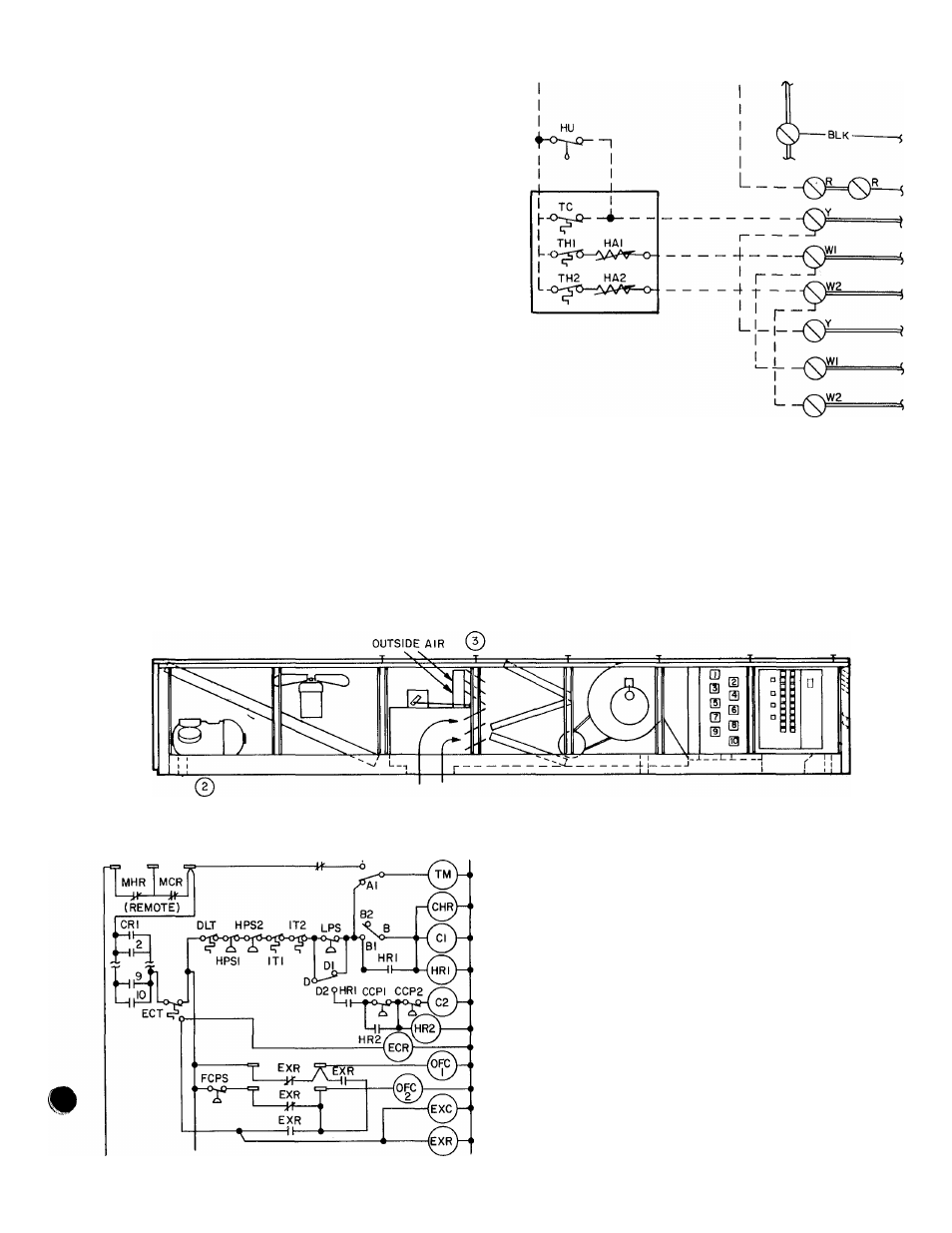
If a zone thermostat calls for cooling while in
economizer mode, a set of cooling relay (CR)
contacts close, energizing the economizer relay
(ECR). See Fig. 14. The ECR is a DPDT plug-in
relay. For economizer damper control, the ECR
locks out the outside air damper adjustable poten
tiometer and shifts the damper control to a Mixed
Air Thermostat (MAT.). The MAT. sensor, located
in the fan section, adjusts the outside air damper to
maintain a preset mixed air temperature (see
Fig. 15).
The 48MA/50ME economizer operation pro
vides economic use of outdoor air for low-cost
cooling. When all zone cooling thermostats are
satisfied, economizer controls are bypassed and the
outdoor dampers are modulated to the minimum
ventilation position. The mixed air temperature
increases, minimizing the amount of reheat re
quired in other zones that require heating.
Refer to Economizer Economics, page 15 to
determine if the addition of an economizer is
justified.
Г
~l
LI
LEGEND
HA
— Heat Anticipator
S)
Hu
- H umidistat
-------
TC
— Thermostat, Cooling -------------------
TH
— Thermostat, Heating ---------------------- Field Wiring
Fig. 12 — Humidistat Connections
Screw Terminal
Printed Circuit
Factory Control Wires
SEQUENCE;
1 — Ambient temperature decreases
2 — Compressor is locked out by economizer control thermostat
3 — Outside air damper is regulated by mixed air thermostat
to maintain fixed mixed air temperature
Fig. 13 — Economizer Operation
LEGEND
C
— Compressor Contactor
CCP
— Capacity Control Pressurestat
CHR
— Crankcase Heater Relay
CR
— Cooling Relay
DLT
— Discharge Line Thermostat
ECR
— Economizer Relay
ECT
— Economizer Thermostat
EXC
— Exhaust Motor Contactor
EXR
— Exhaust Relay
FCPS
— Ean Cycling Pressurestat
HPS
— High Pressure Switch
HR
— Holding Relay
IT
— Internal Thermostat
LPS
— Low-Pressure Switch
MCR
— Master Cooling Relay
MHR
— Master Heating Relay
OFC
— Outdoor Fan Contactor
TM
- Ti mer Motor
Fig. 14 — Economizer Condensing Schematic
13