I ' "1, I 930 i '960' i;'990 r 1030, i 1060 i 1100, I 1140 – Carrier 48MA User Manual
Page 45: 1 " " - ' f, Lo.s, R.,3, Table 4 — fan performance fan performance
Attention! The text in this document has been recognized automatically. To view the original document, you can use the "Original mode".
016
and
024
028
and
030
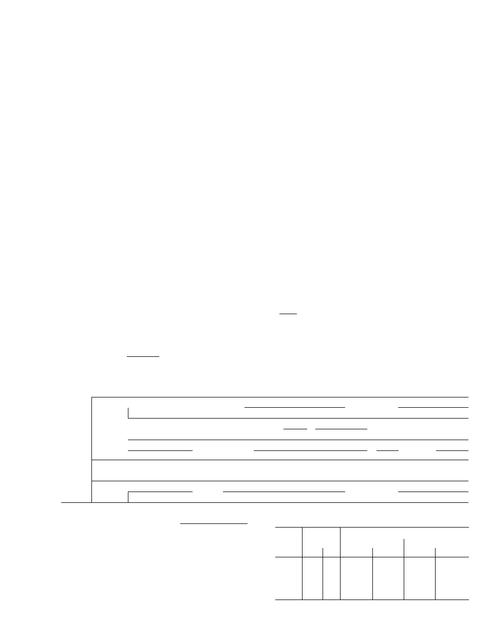
Table 4 — Fan Performance
FAN PERFORMANCE
UNIT
48 M A/
SOME
CFM
0.2
0.4
0.6
EXTERNAL
STATIC
PRESSURE
(in.
wg)
0.8
]
1.0
~J 1.2
[
1.4 1[
1.6
Fan Rpm
Shp
1.8
1
2.2
5.000
6.000
7.000
8.000
9.000
9,600
7.000
8.000
9.000
10,000
11,000
12,000
7.000
8.000
705
760
820
900
955
3.0
1020
3.0
1070
1120
4,4
1170
4.9
I 1220
740
810
880
955
3.0
1020
4,1
1070
46
1130
5.1
1180
5.6
1225
6 . 2
1270
6.S
740
805
3.2
'880
3,8
960
4,2
1020
4.7
1070
5.2
1130
5,S
1190
6.2
1235
7.0
1280
7.7
820
3.9
880
4.4
970
.3.0
1020
1080^
6,i
1 145
6.7
1200
7.3
.’.250.
8.0
1300 I
£2 !
■i....... -■
900
-
980
5.9
1040
1100
7 2
1160
7.9
1215
3.5
1265
4,7
960
6.4
1030
7.Î
1090
7.8
1150
3.3
1205
8.9
1255
9-5
i.
I ' 945 I '995 i 1040
|
1090
5.2
1130
5.8
1180
6.5
1220
7.0
1260
7,6
r
950
i 1
1000
1050
' 5.0
1100
5.7
1150
6 2
1190
6.9
1230
7.5
1270
S-Î
960.
1015
5.C
1070
5,7
1120
6,3
1170
6,9
1210
7 5
1250
8.3
1295
9.3
980
S-Î
1040
s.s
1090
6,3
1140
6,9
T180
7.6
1 230
S.4
1280
9.3
1065
6.3
1115
7.0
1170
7.7
1210
3.7
1255
9,7
I 1300
1
-
rio.s r -
1150 !
' a.o '.]'.
1200
'9,0
1240
10.0
1290
u.o
1
i '
"1
1 " " - ' f
I 930 i '960' i ; ' 9 9 0 r 1030, I 1060 I 1100
-L
I 1140
1__=„
900
940
975
1010
1040
1070
ino I 1155
1200-
9,000
900
930
960
1000
1030
1070
1105
1145
1190
9.9
1220
lO.S
1250
r.,3
034
10,000
970
1 1000 1
1030
!
1070
i
1105
1 1 145
1 1180 1
1210
1 1250
1 1280 !
1320
and
-
!
“ 1
-
1
-
i
1
■98
\
30.5
\
11.2
<■ 32,1
i 33.0 ]
34.0
040
11,000
1045
1 1080 1
1115
[
1150
1 1180
1 1220
1 1250 1 '
1280
1 1320
1 1350 1
1380
-
1
—
\
9,9
I
30,6
r
1 О . 8
\
12.3М
> V3.0- 1
33,8
\
14,5
f 15.3 3
l6-5
12,000
1130
1
1160 1
1195
1 1230
1 1260
! 1295
1 1330 1
1360
1 1390
1 1420 1
1445
11.-2
1
1'5.9
i
12,6
33-,2
1 •4.0
М
14.7- • ■••• О5.8 1
36.2
r- 37.3
f- .36.2 f
39.6
13,000
1210
1 ,1.250... I_
34,5
.1.2.00...
T5,2
1
t
1325
1.6,0.
i
1.350.
37.0
1
T
,1.3.80,
U.B'
-i. J40G
\
..1.4.3Q..
39,2
1 .1460
26,3
1 1480 1
1 23-6 1
14,000
1315
1 1345 !
1370
1 1400
1 1435
1 1460
1 1485 1
1
-
1 - 1
...
Ì7J
J-
Ji±l
18,8
1
2‘X:>
±JiÀ.
f
_L
2Z.8
i
i
«
L_.r 1
NOTES;
1
Italics
indicate
higher
horsepower
motor
is
required
Units
016
and 024 are shown in the same table Underlined italicized values
apply
to
024
only
Units
016
and
024
may
use
10-hp
215T
(NEMA
frame
size)
motor
A
larger
motor
may
not
be
installed
in units 028 and 030 Optional 20-hp motor for units 034 and 040
has
256T
frame
Motor
drives
on
units
024,
028
and
030
are
interchangeable
to
permit
fan
operation
above
or
below
standard
fan speeds
2
Maximum
fan
motor
bhp
is
based
on
conditions
of
minimum
voltage and 80 F air across motor
3.
Fan performance has deductions for unit casing, wet coils, heaters
and clean filters.
4.
Cfm range per module is 600 to 1200 cfm. Lower flow volumes
are
permissible
if
only
first
stage
of
heat
is
operated.
Volumes
above 1200 cfm may cause water blow-off during cooling.
INDOOR AIR FAN MOTOR DATA
UNIT
MOTOR
FAN SPEED (Rpm)
48 MA/
MAX
BHP
Std Motor
Opt Motor
SOME
Std
Opt
Pulley A
Pul ley B
Pulley A
Pulley B
016
5.75
*
880
995
_
_
024
8 60
*
995
1145
_
_
028
11 50
_
1095
1230
_
_
030
11 50
—
1095
1230
—
-
034
17.25
22.8
1095
1230
1320
1425
040
17.25
22 2
1095
1230
1320
1425
‘Field Supplied
43