Miscellaneous – Carrier 48MA User Manual
Page 21
Attention! The text in this document has been recognized automatically. To view the original document, you can use the "Original mode".
Again, 2 jumper wires have to be removed from
the back of the remote panel to isolate the
day/night switch.
MORNING START-UP — To conserve energy and
lower total operating costs, the outdoor dampers
may be closed when starting the system in the
morning. During a warm-up period, when the
system is operated for one or two hours before
occupancy, only building return air should be
heated. The extra load of cold outdoor air intro
duced uses extra heat energy. Ventilation is
unnecessary until space is occupied, so the air
introduced produces unnecessary heat waste.
The same principle holds true on a cooling day,
when outside air transmits heat and moisture to
the evaporator coil. This extra load above the
return air only load is an unnecessary expense.
This can be offset by wiring a heating or
cooling thermostat across the “Short To Close
Dampers” terminals on the zone control board.
The thermostat senses return air temperature and
the outdoor air damper does not open until the
building is at the required temperature.
A time clock can also be used and set as
follows:
1. Occupied cycle: 8 a.m. to 6 p.m. Outdoor air
damper is open and the system is controlled by
individual zone thermostats.
2. Night setback cycle: 6 p.m. to 6 a.m. Individual
zone thermostats are on night setback (NS)
cycle. The outdoor air damper is closed, the
unit is reset down and controlled by NS
thermostat.
3. Warm-up (or cool-down) cycle: 6 a.m. to 8 a.m.
Outside air damper is closed by time clock and
the system is controlled by indoor zone
thermostats.
Using any method, increased economy is
achieved and building requirements are satisfied.
MISCELLANEOUS
Sound and Vibration
— All roof mounted air
conditioning equipment produces sound and vibra
tion. On light types of roof construction, sound
and vibration may be transmitted directly to the
occupied space. Accordingly, sound attenuation
and vibration isolation are important design con
siderations on any rooftop application.
Sound attenuation can be accomplished in
many ways depending on the specific design
construction of the building. Roof mounted units
can be located over unoccupied space (i.e. storage
areas, utility rooms, corridors) where slightly
higher sound levels are not objectionable. Supply
and return duct systems can be acoustically lined
to prevent sound transmission into occupied space.
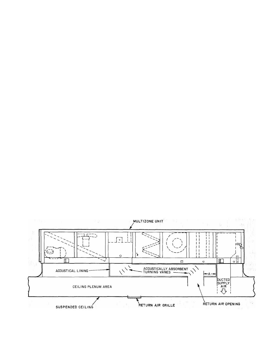
If open plenum return air systems are used, an
acoustical trap or fiberglass-lined chamber can be
used to attenuate the sound. Simple return duct
elbows and tees with 5-ft minimum fiberglass lined
legs and low static pressure drop should be
considered when using open plenum return air
systems. Figure 23 illustrates a procedure for
forming an acoustical trap using the roof curb area
under a 48MA unit.
NOTES:
1 Dimension A is approximately 7 in for optimum performance
2 Acoustical lining is 1-in 1-lb density, neoprene-coated fiberglass
3 Return air grille should be located at least 15 ft from return air opening
Fig. 23 — Acoustical Trap Installation
19