Motor support channel – Carrier 50BA User Manual
Page 9
Attention! The text in this document has been recognized automatically. To view the original document, you can use the "Original mode".
#
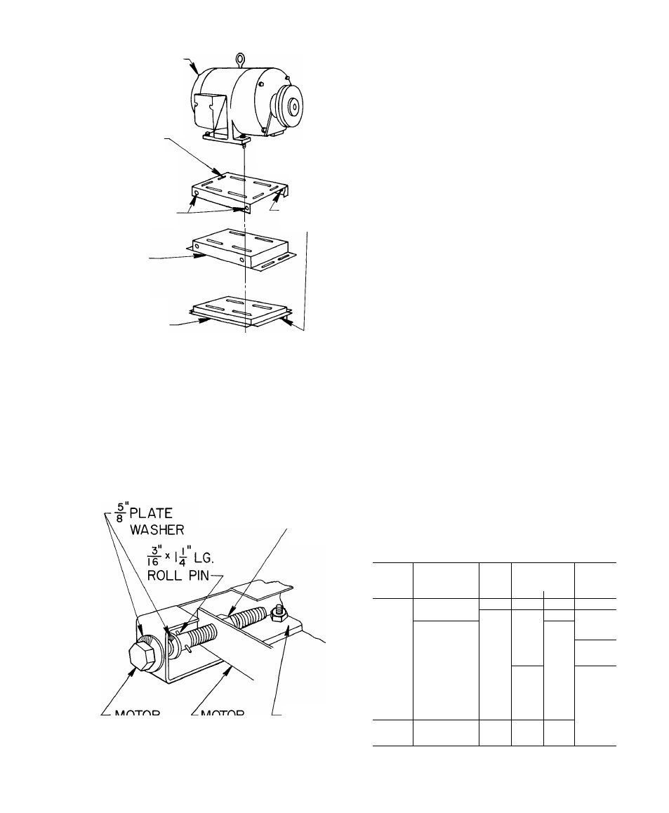
MOUNTING
PLATES
WELD
NUT
FAN MOTOR
50BA,BB
028,034
HOLES
FOR
ADJUSTING
SCREWS
50BA,
BB044
50BA,BB
054,064
Fig. 9 — Motor Mounting
NOTE: On 044 units, motor mounting plate and
channels are factory installed within fan section. No
angle frame plates or fasteners are necessary. In this
position, motor is on right side of fan section.
5. Adjust the following per Installation Step 8:
a. Fan wheel alignment.
b. Shaft alignment.
c. Pulleys.
d. Fan belts.
SUPPORT CHANNEL
WELD NUT-
MOTOR
ADJUSTING
SCREW
MOTOR
SUPPORT
ANGLE
Fig. 10 — Assembled Fan Motor
Adjusting Screw
MOTOR
SUPPORT
CHANNEL
6. Replace panels as follows:
a. Rear coil-section panels, front and rear fan-
section panels.
b. All end panels.
Step 7 — Install fan motor.
This step applies to unit Sizes 50BA,BB028, 034,
054 and 064. Install items after fan-section frame
has'been placed in position on coil section.
NOTE: Place plywood over evaporator coil to pre
vent damage while installing motor and mounts.
To install motor:
1. Fasten motor mounting angle bracket to fan sec
tion. Use Fig. 4 or 5 for position reference and
Fig. 6, 7 and 8 for assembly guidance. Be sure
that lips of angle brackets are around fan-section
frame and that slots for motor mounting plate
face each other.
On Sizes 50BA,BB054 and 064, align bearing
support bracket holes with holes in motor
mounting bracket. Fasten with bolts, flat
washers, lock washers and nuts as shown in
Fig. 8.
2. Position motor on motor plate (Fig. 9) and fasten
with fasteners provided.
3. Fift motor-plate assembly and slide into motor
mounting angles as shown in Fig. 6. Plate fits into
angle slots. On vertical mounts, the motor-frame
assembly may be lowered to the bottom of the
support angle channels.
4. Assemble and install motor adjusting screws as
shown in Fig. 10. Drive roll pins into screws to
prevent screws from backing out during motor
position adjustment.
5. Adjust motor position. Fasten motor mounting
plate to mounting angles.
Table 2 — Alternate Fan Motors and Drives
UNIT
50BA,
BB
NEMA
FRAME
SIZE*
CENTER LINE
FAfVI
HP
DIST>
___ (ir
XNCE
D..„„
SHAFT
DIAM
Max
Min
(in )
004
56
3/4
17.5
15.7
1/2
006
56
1
17 1
15.4
5/8
008,
184, 56, 145T
2
102
6 8
3/4
012
182T, 213
3
102
6 8
016,
024
184, 56, 145T
2
11 8
94
213, 182T
3
11 8
8 4
1
184T, 215
5
11.8
8.4
182T, 213
3
34 4
28 8
028,
184T, 215
5
34 4
28 8
1-3/16
034
254U, 213T
7-1/2
33 3
29 8
256U, 21 5T
10
33 3
29 8
044
213T
21 5T
7-1/2
10
14 3
14.3
10 1
10.1
1-7/16
054,
064
21 3T
7-1/2
33 5
29 0
21 5T
10
33 5
29 0
1-7/16
254T
15
33.5
29.0
•Range of motor sizes unit will accept
NOTE Motors and drives other than those furnished with unit
must be purchased locally