Carrier 50BA User Manual
Page 23
Attention! The text in this document has been recognized automatically. To view the original document, you can use the "Original mode".
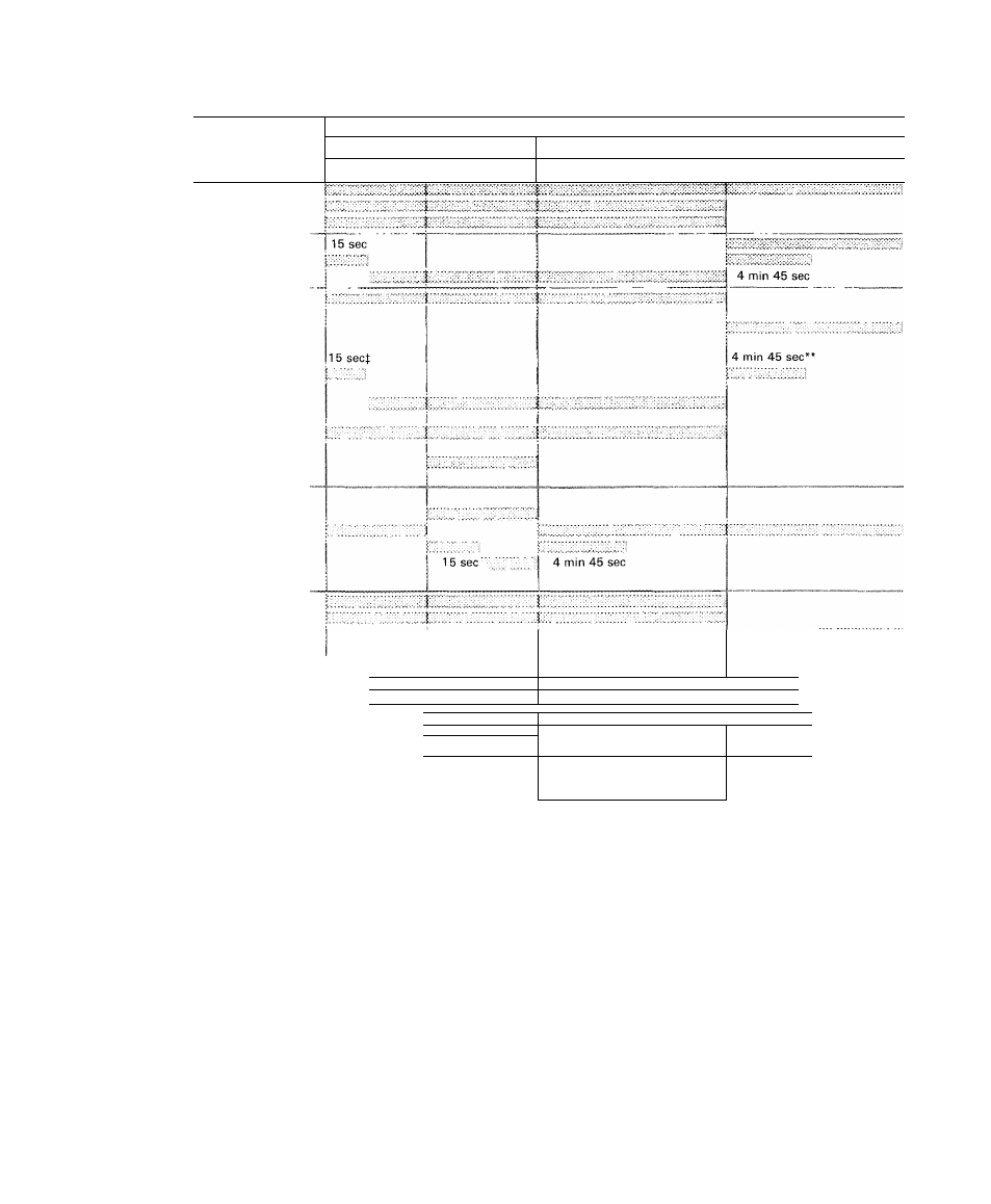
Table 11 — Sequence of Operation with Two-Step Thermostat (016-064)
I
UNIT
50BA.BB
All
Unit
Sizest
044
&
054
All
Unit
Sizest
024
028
034
044
054
064t
BB064
THERMOSTAT
COMPONENT
Calls For Cooling
Satisfied
1st Step 1 2nd Step
2nd Step
1
1st Step
Evaporator Fan
Cooling
Tower*
Pump Motor*
Crankcase Heater #3*
Timer Motor #3
Compressor #3
Air-Cooled Cond #2*
(in on 016)
Crankcase Heater #2*
(#1 on 016)
Timer Motor #2
(#1 on 016)
Compressor #2
(#1 on 016)
Cap Cont Solenoid
(on 064 only)
Liquid Line Solenoid
(on 016 only)
Air-Cooled Cond #1*
Crankcase Heater #1*
Timer Motor #1
Compressor #1
Liquid Line Solenoid #2
Pumpout Relay #2
Crankcase Heater #2
Timer Motor #2
Compressor #2
Cap Cont Solenoid
Low Pressure Switch U2
Liquid Line Solenoid #1
Pumpout Relay #1
Crankcase Heater #1
Timer Motor
Compressor #1
Low Pressure Switch #1
15 sec
30 sec
i
i
4 min 45 sec
! 15 sec
4 min 45 sec
30 sec
........... i:::
Components energized
*When used
fExcept 50BB064
t19 sec (044,054 only)
**6 min 5 sec (044,054 only)
NOTES:
1
If compressor operation is interrupted by protective devices or a
power failure, timer motor will run 4 min 45 sec (or 6 min 5 sec)
before above cycle can be repeated
2
When liquid line solenoid (016) or capacity control solenoid
(064) is energized, it allows refrigerant to flow to complete coil
23