Table 4 — maximum water-side working pressure – Carrier 50BA User Manual
Page 12
Attention! The text in this document has been recognized automatically. To view the original document, you can use the "Original mode".
WATER-COOLED
UNITS,
SIZE
50BA004
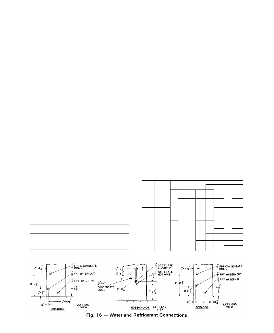
THRU 012 — Connect condenser water supply and
return lines as indicated in Fig. 16 and 17. When
connecting water lines, hold the condenser inlet and
outlet stubs firmly with a wrench at the FPT hex
fitting to prevent twisting. Do not use water lines
smaller than connection sizes shown in Fig. 17.
Observe all applicable plumbing and sanitary codes.
To assemble Carrier Compatible Fittings:
1. Cut tubing to length with tube cutter and remove
burrs.
2. Mark required insertion depth on tube (1-1/4 in.
for 5/8- and 3/4-in. OD tubing).
3. Remove plug from fitting and loosen nut one
turn.
4. Position and insert tube into fitting. Bottom
tube past depth mark.
5. Leave nuts on condenser end of tubing. Loosen
and purge one line at a time, using holding
charge in base unit.
6. Tighten nuts to stop on unit fitting collar.
7. Open all service valves.
Make sweat connections as follows:
1. Clean tube; then remove plug and nut from
fitting.
2. Remove O-ring from inside fitting with bent pin.
3. Wrap entire valve with wet rag.
4. Bottom tube in fitting and apply low temperature
solder, such as Allstate 430.
If specified, install field-supplied water-regulating
valve in water supply line outside cabinet as
follows:
1. Route the regulating valve capillary with its flare
nut to the fitting on refrigerant liquid line (Fig. 2),
using any convenient unused opening on side of
unit. Use a grommet in unit panel to prevent
chafing of capillary.
Table 4 — Maximum Water-Side
Working Pressure
UNIT SIZE 50BA
MAXIMUM WORKING
PRESSURE
004,006,008,012
450 psig
016
550 psig
024,028,034,044,054,
150 psig*
064
250 psig
2. Remove cap from liquid line fitting.
3. Remove cotter pin taped to liquid line near
fitting. Insert pin, split end first, into water
regulating valve flare nut.
4. Connect flare nut to fitting. Round end of cotter
pin will depress core of fitting. The opened
fitting allows refrigerant pressure to act on water
regulating valve. Tighten flare nut to prevent
leakage.
The fitting automatically seals (closes) when flare
nut is removed; a slight amount of refrigerant is lost
each time, however. Do not lose cotter pin.
WATER-COOLED UNITS, SIZE 016 THRU 064
— Connect condenser water supply and return lines
as indicated in Fig. 16. Unit Size 50BA024, 044, 054
and 064 require field modification to condenser
piping when used on city or waste water. Refer to
Fig. 18, 21 and 24.
Install a water regulating valve on the inlet of each
condenser with any size unit used on waste or city
water (Fig. 19,20,22,23 and 24). Connect regulating
valve capillary to a back-seated liquid service valve.
Arrow on valve body must point in direction of
liquid flow. After connecting capillary, open
regulating valve one turn from back-seated position.
Adjust valve to maintain proper condensing
temperature.
Install a full size gate valve and strainer in water
supply line. Valve and strainer must be accessible.
See Table 4.
Table 5 — Recommended Line Sizes (in.)
(Condenserless Models)
*550 psig if factory-installed dresser adapters are removed and
field-fabricated manifold is installed
UNIT
50BB
CONN
LENGTH OF LINE
SYSTEM
SIZES*
20
40
60-80
L
HG
L
HG
L
HG
L
HG
004
—
1/2
1/2
1/2
1/2
1/2
5/8
1/2
7/8
006
—
1/2
1/2
1/2
7/8^
1/2
7/8
5/8
7/8
008
—
1/2
7/8
1/2
7/8
1/2
7/8
1/2
7/8
012
-
5/8
7/8
5/8
7/8
5/8
1-1/8
3/4
1-1/8
016
—
5/8
1-1/8
5/8
1-1/8
7/8
1-1/8
7/8
1-3/8
024
1 & 2
5/8
7/8
5/8
7/8
5/8
ï-i/8
7/8
1-1/8
028
1
5/8
1-1/8
5/8
1-1/8
7/8
1-1/8
7/8
1-3/8
2
5/8
7/8
5/8
7/8
5/8
1-1/8
7/8
1-1/8
034
1 & 2
5/8
1-1/8
5/8
1-1/8
7/8
1-1/8
7/8
1-3/8
044
1 & 2
5/8
1-1/8
5/8
1-1/8
7/8
1-1/8
7/8
1-3/8
3
5/8
7/8
5/8
7/8
5/8
1-1/8
7/8
1-1/8
054
1,2,3
5/8
1-1/8
5/8
1-1/8
7/8
1-1/8
7/8
1-3/8
064
1 & 2
7/8
1-3/8
7/8
1-3/8
7/8
1-5/8
7/8
1-5/8
HG — Hot Gas Line (OD
L — Liquid Line (OD in
in )
)
*Sweat connections
12