Table 7 — electrical data, Step 16 — make electrical connections – Carrier 50BA User Manual
Page 16
Attention! The text in this document has been recognized automatically. To view the original document, you can use the "Original mode".
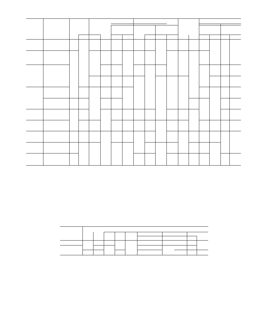
-> Table 7 — Electrical Data
COMPRESSOR NO. 1
COMPRESSOR NO. 2
POWER SUPPLY
VULI-
IIMUUUK
UNIT
50BA.BB
VOLTS/PH/HZ
AGE
RANGE
RLA
LRA
RLA
LRA
FAN
MOTOR*
Min
Ckt
Ampst
MOCP
Ampst
Min
Max
BA
BB
BA
BB
BA
BB
BA
BB
Hp
FLA
BA
BB
BA
BB
230/1/60
207
253
19 8
19 8
88 0
88 0
_
_
_
_
1/3
33
28 1
28 1
45
45
004
208-230/3/60
187
253
13 0
13 0
87 0
87 0
_
—
—
—
1/3
3 3
19 6
19 6
30
30
460/3/60
414
528
5 5
5 5
30 0
30 0
—
—
—
—
1/3
0.8
7.7
7,7
15
15
230/1/60
207
264
27 9
39 0
106 0
135 0
—
__
—
—
3/4
5 3
40 2
54 1
70
90
006
208-230/3/60
187
253
18 3
20 6
105 0
136 0
—
—
--
3/4
7 1
30 0
32 9
45
50
460/3/60
414
528
88
104
35 0
49 0
—
_
_
—
3/4
7
6
12 6
14 6
20
25
575/3/60
518
632
64
84
27 0
41 0
—
_
_
—
3/4
1 1
9 1
11,6
15
25
208-230/3/60
187
253
23 7
31 3
184 0
137 0
_
_
_
—
1
40
33 7
44 0
50
70
008
460/3/60
414
506
11 4
14 1
69 0
62 0
—
—
—
_
1
1 6
15 9
194
25
30
575/3/60
518
632
96
11 3
55 0
50 0
—
—
—
—
1
1 4
134
15 5
20
25
208-230/3/60
187
253
36 3
40 0
137 0
170 0
—
_
_
2
60
52 0
56 0
80
90
012
460/3/60
414
506
14 6
180
62 0
77 0
—
—
—
—
2
2 8
21 1
25 9
35
40
575/3/60
518
632
11 4
14 4
50 0
62 0
—
—
—
—
2
23
16 6
20.7
25
35
208-230/3/60
187
253
50 0
64 0
191 0
266 0
—
--
—
—
2
70
70 0
87 0
110
150
016
460/3/60
414
506
22 1
29 0
86 0
120 0
—
—
—
—
2
3 1
31 0
40 0
50
50
575/3/60
518
632
17 9
23 0
69 0
96 0
—
—
~
—
2
2 5
25 0
32 0
40
35
208-230/3/60
187
253
36 0
45 0
1370
170 0
36 0
45 0
137 0
170 0
3
9 2
91 0
1110
125
150
024
460/3/60
414
506
16 0
20 0
62 0
77 0
160
20 0
62 0
77 0
3
46
40 8
49 8
50
60
575/3/60
518
632
12 9
16 0
50 0
62 0
129
16 0
50 0
62 0
3
3 4
32 9
40 0
45
45
208-230/3/60
187
253
49 3
64 0
191 0
266 0
35 7
45 0
137 0
170 0
5
16 2
1140
142 0
150
200
028
460/3/60
414
506
22 2
29 0
86 0
120 0
16 0
20 0
62 0
77 0
5
66
51 4
63 9
60
70
575/3/60
518
632
180
23 0
69 0
96,0
130
170
50,0
62.0
5
5,6
41.0
51.9
45
70
208-230/3/60
187
253
49 3
64 0
191 0
266 0
49 3
64 0
191 0
266 0
5
16 2
128 0
161 0
175
200
034
460/3/60
414
506
22 2
29 0
86 0
120 0
22 2
29 0
86 0
120 0
5
6 6
57 6
72 9
60
80
575/3/60
518
632
180
23 0
69 0
96 0
180
23 0
69 0
96 0
5
5 6
46.0
57 9
50
80
208-230/3/60
187
253
50 0
64 0
191 0
266 0
36 0
45 0
137 0
170 0
7-1/2
21 6
171 0
211 0
200
250
044t
460/3/60
414
506
23 0
29 0
86 0
120 0
160
20 0
62 0
77 0
7-1/2
9 5
77 0
95 0
90
110
575/3/60
518
632
180
—
69 0
—
130
—
50 0
—
7-1/2
8 4
62 5
—
80
—
208-230/3/60
187
253
50 0
64 0
191 0
266 0
50 0
64 0
191 0
266 0
10
28 0
191 0
236 0
225
300
054t
460/3/60
414
506
23 0
29 0
86 0
120 0
23 0
29 0
86 0
120 0
10
13 0
88 0
107 0
100
125
575/3/60
518
632
180
—
69 0
—
180
—
69 0
—
10
105
69 5
—
80
~
208-230/3/60
187
253
102 0
1190
506 0
506 0
102 0
119 0
506 0
506 0
15
46 2
276 0
314 0
350
400
064
460/3/60
414
506
50 0
50 0
253 0
253 0
50 0
50 0
253 0
253 0
15
21 0
134 0
134 0
175
175
575/3/60
518
632
38 0
50 0
176 0
176 0
38 0
50 0
176 0
176 0
15
16 4
102 0
129 0
125
175
FLA
Hp
LRA
MOCP
RLA
Full Load Amps
Horsepower
Locked Rotor Amps
Maximum Overcurrent Protective Device (See Note 1 )
Rated Load Amps
"Indoor fan motors are 3-phase motors of same voltage as unit except those
with FLA values in italics These motors are single-phase motors of same
voltage as unit
tMin Ckt Amps and MOCP Amps values per NEC (See Note 1 )
iUnits 50BA,BB044 and 054 have 3 compressors Compressor no 1 data
applies to Systems 1 and 2; compressor no 2 data applies to System 3
NOTES;
• 1 In compliance with NEC requirements for multimotor and combination
load equipment (NEC Articles 430 and 440}, the overcurrent protective
device for the unit shall be fuse only
2 Phase imbalance must not exceed 2%
3 Fan motor power wiring, circuit breakers and other electrical components
are sized to accommodate special motors on the 50BA,BB016,024,028
and 034 units
4 Wire sizing amps are a sum of 125% of the FLA for largest motor plus
100% of FLA for all other motors in the unit
5 Maximum instantaneous current flow during starting is the sum of the
LRA for last compressor to start plus the FLA for all other compressors
in the unit
Table 8 — Maximum Wire Sizes for
Terminal Block (AWG or MCM)*
VOLT/
PHASE
UNIT 50BA,BB
008
012
016
024
028,
034
044
054
064
BA 1 BB
BA
BB
BA
BB
208 230/3
00
00
00
00
350
0000 350
350
350
350
500
460/3
00
00
00
00
00
00 ÒÒÓ0
0000
0000
350
350
575/3
00
00
00
00
00
00 1 —
00
-
350
350
’Terminal block not supplied on 004 and 006 unit sizes Wire size to be selected per NEC and supply
wires to be connected to factory-supplied pigtail wire connectors
’Step 16 — Make electrical connections.
GENERAL — Provide an adequate fused dis
connect switch per NEC within sight of the unit.
Provision for locking switch open (OFF) is ad
visable to prevent power from being turned on when
unit is being serviced.
On 50BA,BB016 thru 064 size units, power may
be supplied thru a branch circuit. Branch circuit
protection is provided in these units by manual reset
circuit breakers. Branch circuit must be in accord
ance with NEC or local code, whichever takes
precedence. Power supplied to auxiliary equipment,
such as fan motors for air-cooled condenser or for
cooling tower, must be run separately.
POWER WIRING — Conduit opening for 50BA,
BB004 thru 012 units is on left side of unit near
control box; for 50BA,BB016 thru 064 units, the
opening is on back of unit near control box.
i