Carrier 50BA User Manual
Page 11
Attention! The text in this document has been recognized automatically. To view the original document, you can use the "Original mode".
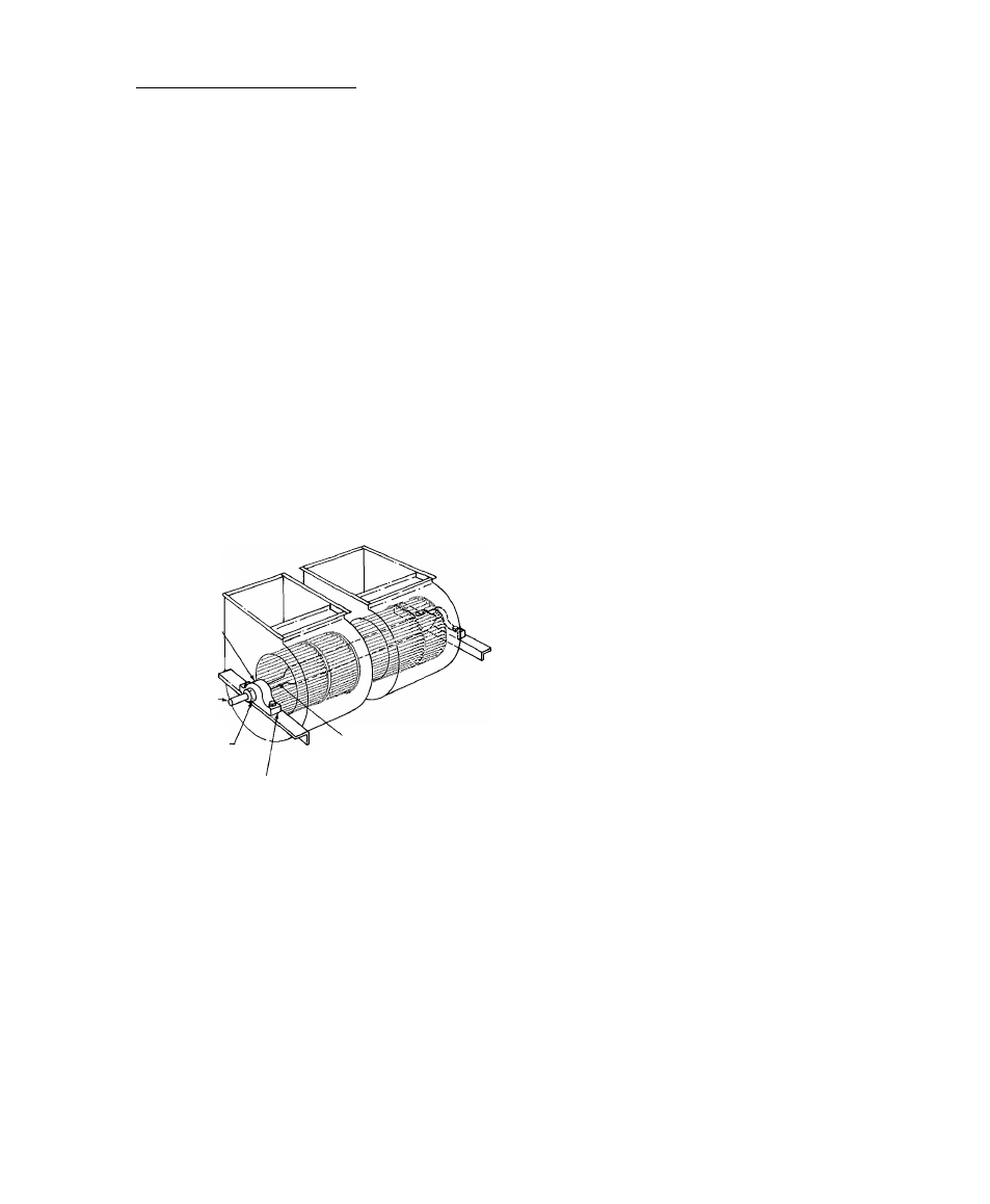
Unit Sizes 5QBA028 thru 064 — Bearings are bolted
to an angle support fastened to fan scroll (Fig. 15).
To correct shaft and wheel concentric misalignment:
1. Loosen bearing support bolts and shim or move
as required.
2. Retighten bearing support bolts.
HORIZONTAL SHAFT ALIGNMENT (All units)
— If the shaft has moved and all wheels are off
horizontal center, recenter the shaft as follows:
1. Loosen the setscrews holding bearing locking
collar at each end of shaft (Fig. 14 or 15).
2. Slide shaft and wheel assembly horizontally until
wheels are horizontally centered (Fig. 11).
3. Slide the bearing locking collars against the bear
ing race and turn in direction of shaft rotation
until tight.
4. Retighten locking collar setscrews.
CUTOFF CLEARANCE (Unit Sizes 044, 054 and
064) — After centering and aligning the fan wheel,
loosen cutoff sheet (Fig. 13), adjust for 1-1/4 in.
clearance as shown and then tighten securely.
FAN, PULLEY AND BELT ADJUSTMENT
Refer to the Service section entitled Indoor-Air
Fan Adjustment.
PILLOW BLOCK
FAN SHAFT
BEARING.
SHAFT EXTENSION
LONGER ON
ONE END TO
ACCOMMODATE
DRIVE PULLEY
BEARING LOCKING
COLLAR 2 SET SCREWS
'HOLLOW SHAFT
3 FANS ON 028-064
'SHIM IF NECESSARY
Fig. 15 — Horizontal Shaft Alignment
Step 9 — Install heating coil if supplied.
On 50BA,BB004 and 006 units, any water or
steam heating coil must be installed thru the back
of the unit as described in the Installation Instruc
tions shipped with the accessory coil.
Step 10 — Install supply air (evaporator)
ductwork.
Connect supply ducts to flanges on air supply
opening (Fig. 1), using a flexible connection.
Attach ductwork to building structure and insu
late with fiberglass and vapor barrier to prevent
sound transmission and vapor condensation.
Weatherproof external ductwork, joints and
openings with flashing and mastic in accordance
with applicable codes.
Ducts passing thru an unconditioned space must
be insulated and covered with a vapor barrier.
Step 11 — Install return air ductwork (004 —
012 units).
The unit back panel is stamped to indicate alter
nate return air (or outdoor air inlet) opening as
indicated in Fig. 1.
1. Cut out the alternate return air opening as
required.
2. Attach a 1-in. flange to unit back panel or attach
a flanged, flexible duct connection directly to
unit as desired.
If an outdoor makeup air damper is to be in
stalled, attach it directly to unit back panel and
install flexible connection between damper
assembly and remaining ductwork.
Use accepted ductwork installation procedures.
Follow all applicable codes.
3. Restrict or completely blank off the standard
return air opening with a field-fabricated filler
panel. This panel must be removable for service
access. Refer to Service section entitled Return
Air Grille Removal as required.
Step 12 — Check return-air filters.
Be sure filters shipped with unit are the correct
size (see Table 1). Never operate unit without return-
air filters in place.
Step 13 — Check compressor spring mounts
(50BB008 and 50BA,BB012 thru 064).
The compressors are held rigid in shipment by
bolts extending thru a washer, grommet and com
pressor foot into a weld nut (for 064 unit, see para
graph below).
Loosen each bolt (4 per compressor) until com
pressor floats freely on springs. Then retighten bolts
until there is slight pressure on the neoprene gasket.
This will steady the compressor and prevent
start and stop rocking.
The 50BA,BB064 units are shipped with 4 special
flanged washers and neoprene grommets in a cloth
bag tied to the compressor. Remove the compressor
hold-down bolts. Then install the neoprene
grommets between the compressor feet and the
special washers. Reinstall the hold-down bolts and
tighten until there is slight pressure on the
grommets.
The compressors have reversible oil pumps that
operate in either direction; therefore the direction
of rotation need not be checked.
NOTE: Do not loosen bolts on 50BA008
compressor.
Step 14 — Make condenser connections.
WATER-COOLED (50BA) UNITS ^ GENERAL
— Condensers have water inlet and outlet connec
tions as shown in Fig. 16. Piping arrangements for
city, waste or recirculating water are shown in
Fig. 17 thru 24.
11