Carrier 50BA User Manual
Page 10
Attention! The text in this document has been recognized automatically. To view the original document, you can use the "Original mode".
Step 8 — Align fan shaft and wheel.
HORIZONTAL WHEEL CENTERING — All
wheels must be horizontally centered between the
inside edges of their fan scroll venturis (Eig. 11).
WHEEL
VENTURI
/SCROLL
MUST BE EQUAL ALL AROUND
Fig. 11 — Horizontal Wheel Centering
Adjust as follows:
Unit Sizes 50BA,BBQ04 thru 024
1. Loosen setscrews holding wheel support to shaft
(Eig. 12).
2. Center the wheel by sliding it horizontally.
3. Retighten setscrews.
Unit Sizes 50BA'BBQ28 thru 064
1. Loosen fan wheel locking clamps on each side
of fan support (Fig. 12).
2. Center the wheel by sliding it horizontally.
3. Retighten locking clamp bolts to torque speci
fied in Table 3.
Table 3 — Torque Requirements
BOLT SIZE (in.)
FAN CLAMP BOLT
RECOMMENDED TORQUE (Ib-ft)
5/16
7/16
15-18
30-35
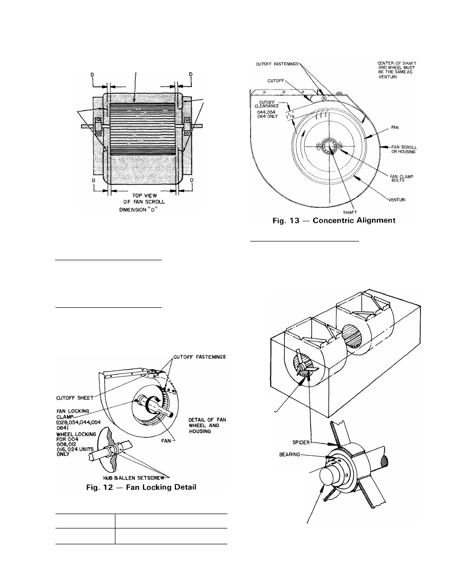
CONCENTRIC
ALIGNMENT
Shaft
and
wheels must be concentrically centered with the
venturi or air inlet of the fan housing (Fig. 13).
Unit Sizes 50BA,BB004 thru 024 — Shaft bearings
are supported by spider (Fig. 14). If shaft and wheels
are concentrically misaligned from shipping shock,
it is possible to rebend spider arms to original posi
tions. Replace the spider if it has been extensively
damaged by shipping shock.
VENTURI
LOCKING COLLAR
SHAFT
Fig. 14 — Fan Shaft Bearings — 004,006,
008,012,016,024
10