Carrier 50BA User Manual
Page 19
Attention! The text in this document has been recognized automatically. To view the original document, you can use the "Original mode".
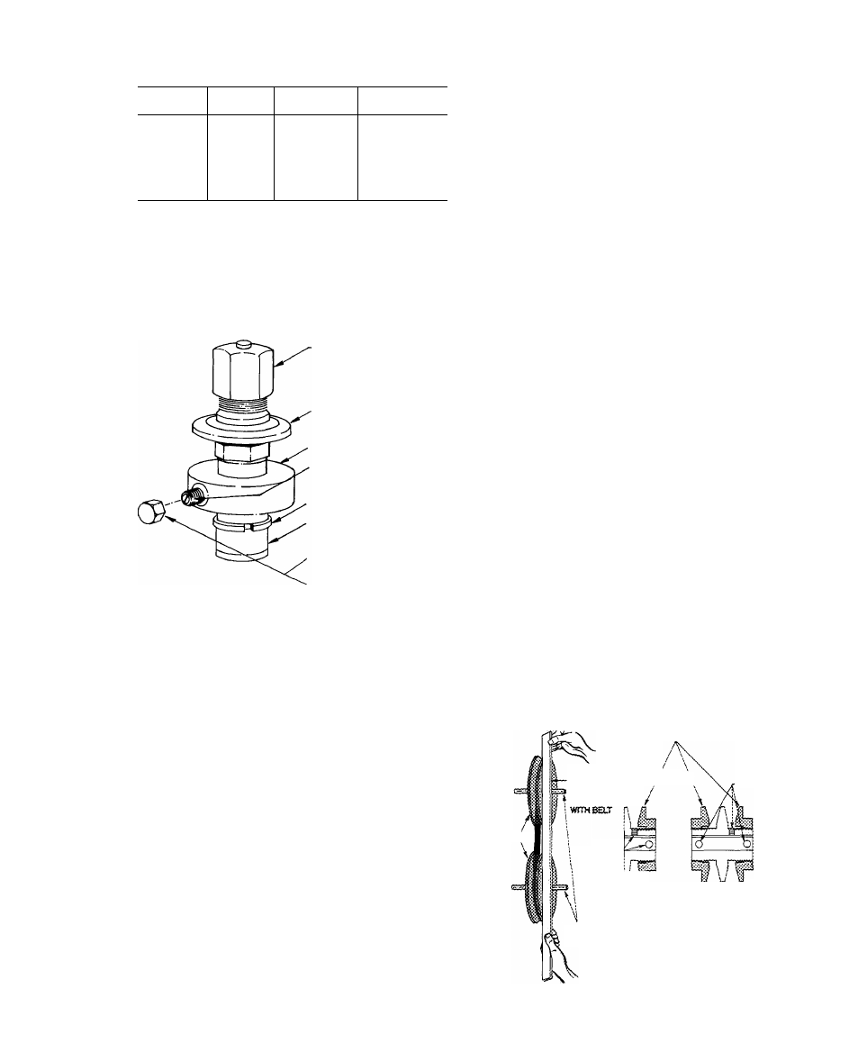
Table 10 — Factory Set Points (psig)
UNIT
50BA.BB
ACTION
UNLOADER
NO. 1
UNLOADER
NO. 2
012
Load
Unload
69
58
—
016
Load
Unload
69
58
—
064
Load
Unload
77
58
74
55
TO REGULATE CONTROL SET POINT
E Turn adjustment nut (Fig. 29) clockwise to its
bottom stop. Set point is now 85 psig.
2. Turn adjustment nut counterclockwise to reach
desired pressure. Each full turn decreases the set
point by 7.5 psig. (Approximately 11-1 /2counter
clockwise turns decreases set point to 0 psig.)
-CONTROL SET POINT
ADJUSTMENT NUT
POWER HEAD
VALVE BODY
PRESSURE DIFFERENTIAL
ADJUSTMENT SCREW
BYPASS RSTON RING
BYPASS PISTON
DIFFERENTIAL SCREW
SEALING CAP
REPLACE CAP TO PREVENT
REFRIGERANT LEAKAGE
Fig. 29 — Capacity Control Valve
TO ADJUST PRESSURE DIFFERENTIAL -
Turn differential adjustment screw (Fig. 29)
counterclockwise to its back-stop position. Differ
ential is now 6 psig.
Then turn screw clockwise to desired differential.
Each full turn increases differential by 1.6 psig.
(Approximately
10
clockwise
turns
increases
differential to 22 psig.)
SERVICE
CAUTION: Before sert'icing fair compartment;
E Sharp edges of ex'aporator coU fms are ex
posed, To prevent arm injury, cover top edge
of evaporator with cardboard strip or a few
layers of heavy tape.
2. To avoid coil damage, ctjver evaporator coil
face with ply^vood or other rigid sheet
tnaterial. If any coil fins are mashed or bent,
straighien with a coil ftn comb of the proper
tooth spacing (see coil fins/in. in Table i).
Check for refrigerant leaks.
Indoor Air Fan Adjustment
— Observe fan com
partment CAUTION note above. The fan motor
pulleys are factory set at the fan speeds listed in
Table 1. Unit Sizes 50BA,BB044,054 and 064 have
fixed pulleys.
TO CHANGE FAN SPEED (004-034)
1. Shot off unit power .supply.
2. Loosen fan belt by loosening fan motor from
mounting bracket. Do not loosen fan motor
mounting bracket from unit.
3. Loosen movable pulley flange setscrew (Fig. 30).
4. Screw movable flange toward fixed flange to
increase fan speed and away from fixed flange to
decrease speed, using values shown in Table 1.
Increasing fan speed increases load on motor. Do
no! exceed maximum allowable fan speed (Table
I) or motor full load amps indicated on motor
nameplate and Table 7.
5. Set movable flange setscrew at nearest flat of
pulley hub and tighten setscrew.
6. Check Pulley Alignment and Belt Tension Ad
justment as described below.
7. Check fan operation. Repeat above procedure
as required.
PULLY ALIGNMENT — Shut off unit power
supply. Loosen fan motor pulley setscrews and
slide fan pulley along fan shaft. Make angular align
ment by loosening motor from mounting bracket.
See Fig. 30.
BELT TENSION ADJUSTMENT - Shut off
unit power supply. Loosen fan motor from
mounting bracket. Do not loosen motor mounting
bracket from unit. Move fan motor up or down until
proper belt tension is achieved (approximately
3/4-in. deflection with 8-lb tension at midpoint of
belt span).
MOVABLE FLANGES (004-034 ONLY)
PULLEYS,
STRAIGHT EDGE /
\
MUST BE
PARALLEL
SETSCREWS
SETSCREWS'
;/ <1
^FIXEO
flanges
^
SINGLE-GROOVE TWO-GROOVE
MOTOR BFAN SHAFTS
MUST BE PARALLEL
Fig. 30 — Indoor Air Fan Pulley Adjustment