Carrier 50BA User Manual
Page 15
Attention! The text in this document has been recognized automatically. To view the original document, you can use the "Original mode".
R£aRCUtAT{«6 SYBTeiiS - S£S NOTH )
NOTE For waste or city water, remove inlet manifold and supply
condensers individually
"Fig. 24 — 50BA064 Condenser Water Piping
50BA.BB*
COIL NO.
COMPR NO.
CONO NO.*
016
1
1
1
024,028,
034,064
1, 2
1, 2
1, 2
044,054
1, 2, 3
1,2,3
1, 2, 3
*50BB units are condenserless
Fig. 25 — Refrigeration Circuits (016-064)
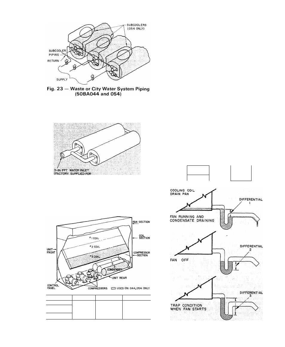
Step 15 — Install unit drain line.
Install a trapped condensate drain line at unit
drain connection (Fig. 16). The drain requires
standard pipe connected to condensate pan nipple
as shown in Table 6. Figure 26 shows proper trap
design.
Determine design negative static pressure. This
pressure is not the same as fan total pressure, which
includes pressure losses downstream as well as
upstream from the indoor air fan. Always assume
the worst conditions, such as having return air filters
clogged with dirt.
Referring to Fig. 26, Differential 1 must be equal
to or larger than negative static pressure at design
operating conditions. Store enough water in trap to
prevent losing seal (Differential 2). This differential
must be equal to or larger than one-half the maxi
mum negative static pressure. When the fan starts.
Differential 3 is equal to the maximum negative
static pressure.
Do not use drain line smaller than size listed in
Table 6. If required, cut hole in panel for drain line.
Pitch drain downward toward an open drain sump.
Provide a trap at least 3 in. high with plugged tee for
cleaning. Fill trap with water to make an air seal.
Observe all sanitary codes.
Table 6 — Condensate Drain Connections (in.)
UNIT SIZE
004,006,
008,012
016,024
028,034,
044,054
3/4
1
1-1/4
064
1
-
1/2
Fig. 26 — Condensate Drain
IS