Carrier 50BA User Manual
Page 8
Attention! The text in this document has been recognized automatically. To view the original document, you can use the "Original mode".
2.
3.
4.
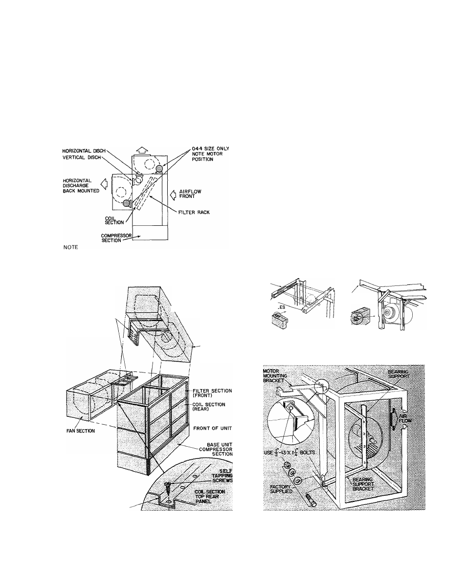
Lift and position fan section on rear of coil section
(Fig. 4). Secure with fasteners provided.
Install the following per Installation Step 7:
a. Motor mounting frame angles.
b. Motor on plate assembly.
c. Motor-plate assembly on frame angles.
d. Balance of drive package components.
Adjust the following per Installation Step 8:
a. Shaft alignment.
b. Fan wheel position.
c. Pulleys.
d. Fan belts.
VERTICAL DISCH
TOP MOUNTED
Motor pulley on left side of unit — vertical discharge
Motor pulley on right side of unit — horizontal discharge
Fig. 4 — Fan and Motor Arrangements
50BA,BB028,034,044,054,064
MOTOR MOUNTING
BRACKETS (INSTALL
AFTER MOUNTING
fan
SECTION)
REAR HORIZONTAL FAN
AND VERTICAL FAN
DISCHARGE SOBA.BB
028,034,044,054
\ AND 064
FAN SECTION
NO MOTOR MOUNTING
BRACKET USED WITH
044 SIZE UNIT
THREE FANS ON 054 AND
064 UNITS
REAR PANEL FAN SECTION
Fig. 5 — Fan Section Mounting
(50BA,BB028-064)
5. Replace panels as follows:
a. Rear coil section panel on top of coil section.
Rear holes will overlap fan section top panel.
Fasten, using hole vacated in Step Ic (see
Fig. 5).
b. All end panels.
NOTE; On Size 044 units, motor mounting channels
are factory installed and no angles, plates or
fasteners are necessary. In this position, the fan
motor is located on right side within fan section.
To set up Sizes 50BA,BB028 thru 064 for vertical
air discharge (Fig. 4 and 5):
1. Remove:
a. Front, rear and end panels of fan section.
Upper-rear and end panels of coil section.
Filters from coil section.
Fasteners holding filter frame top. Push frame
out and away from coil section frame (on 028
and 034 units only).
2. Lift up and position fan section on coil section
(Fig. 5).
3. Fasten fan-section frame to coil-section frame
with fasteners provided, then (on 028 and 034
units) reposition and fasten the filter frame
moved in Step Id.
4. Install the following per Installation Step 7;
a. Motor mounting frame angles.
b. Motor on motor-plate assembly.
c. Motor-plate assembly on frame angles.
d. Balance of drive package components.
b.
c.
d.
MOTOR MOUNTING
ANGLES
ADJUSTING
SCREW HOI
FAN SECTION
FRAME
Fig. 6 — 028 and 034
Horizontal Fan Motor
Mounting Angles
Fig. 8 — Fan Motor Mounting Detail
(50BA,BB054 and 064)
Fig. 7 — 054 and 064
Vertical Fan Motor
Mounting Angles
I