Single-stage heat a cool- manual changeover, Single-stage heat 8 cool- autochangeover, Fig. 8 — high- and low-voltage connections – Carrier 48KH User Manual
Page 8: Table 3 — electrical data (60 hz)
Attention! The text in this document has been recognized automatically. To view the original document, you can use the "Original mode".
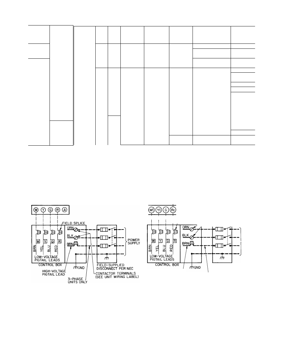
Table 3 — Electrical Data (60 Hz)
MODEL
48-
SERIES
KL018
300BE
KL024
300BE
KH024
300BE
KL030
300BE
KH030
300BE
" '
зоове
"“
KL036
500CE
600CE
KH036
_300BE/BF
500C
e
7
c
F
KL042
300BE
' 50ÒCÉ
KH042
300BE
5Ó0CE
300BE
KL048
500CE
600CE
KH048
300BE/BF
” 5ÓÒCE/CF
KL060
300BE
KH060
300BE/BF
V-PH
OP
von
RAr
Min
ER
AGE
OGE
Max
FULL LOAD
AMPS
MAX FUSE
SIZE (Amps)
MINIMUM
AMPACITY
FOR WIRE
SIZING
MINIMUM
WIRE SIZE (AWG)
(60 or 75 C Copper)*
MAX WIRE
LENGTH
(ft)*
208-230-1
197
253
11 5
20
13 9
14
70
208-230-1
197
253
17 2
30
20 9
10
120
208-230-1
197
253
18 5
30
22 2
10
110
208-230-1
197
253
19 8
35
23 8 /
10
102
208-230-1
197
253
19 6
35
23 6
10
102
208-230-1
197
253
24 3
40
29 0
10
83
208/230-3
187
253
17 4
35
20 4
10
143
460-3
414
506
7 6
15
8 9
14
310
208-230-1
197
253
23 3
40
28 0
10
88
208/230-3
187
253
18 3
35
21 3
10
135
208-230-1
197
253
28 8
50
35 0
8
115
208/230-3
187
253
21 9
40
25 8
10
115
208-230-1
197
253
28 6
50
34 6
8
ÌT2 “
208/230-3
187
253
21 3
40
25 2
10
118 ..........
208-230-1
197
253
30.1
50
36 0
8
105
208/230-3
187
253
24 8
40
28 5
10
103
460-3
414
506
11 5
20
13 2
14
200
208-230-1
197
253
29 3
50
35 2
8
108
208/230-3
187
253
22 8
40
26 5
10..................
110
230-1
207
253
35 9
60
42 9
(6)[8]t
(155)[100]t
230-1
207
253
36 2
60
43 2
(6)[8]t
(150)[120]t
*Wire sizes are based on 60 or 75 C copper wire at 86 F (30 C)
ambient temperature and the minimum ampacity If other than
60 or 75 C copper wire is used, if the ambient temperature is
above 86 F (30 C), or if the voltage drop of the wire exceeds 2% of
the total rated voltage, determine the wire size from the minimum
ampacity shown and the National Electrical Code Wire lengths
shown are measured one way along the wire path between the
unit and service panel
fData in parentheses are based on 60 C copper wire Data in
brackets are based on 75 C copper wire
SINGLE-STAGE HEAT a COOL-
MANUAL CHANGEOVER
SINGLE-STAGE HEAT 8 COOL-
AUTOCHANGEOVER
JUMPER^
CONTACTOR TERMINALS
i FIELD SPLICJ^(SEE UNIT WIRING LABEL)
^POWER
SUPPLY
HIGH-VOLTAGE
PIGTAIL LEAD
FIELD-SUPPLIED
DISCONNECT PER NEC
3-PHASE
UNITS ONLY
. Field Low-Voltage Wiring
. Field High-Voltage Wiring
. Factory Low-Voltage Wiring
. Factory High-Voltage Wiring
NOTE For manual changeover applications, use thermostat part no HH01AD042 with
subbase part no HH93AZ042; or thermostat part no HH01AD040 with subbase part no.
HH93AZ040
For automatic changeover, use thermostat part no HH07AT174 with subbase part no
HH93AZ096; or thermostat part no HH10AD041 with subbase part no HH93AZ041
Fig. 8 — High- and Low-Voltage Connections