Carrier 48KH User Manual
Page 6
Attention! The text in this document has been recognized automatically. To view the original document, you can use the "Original mode".
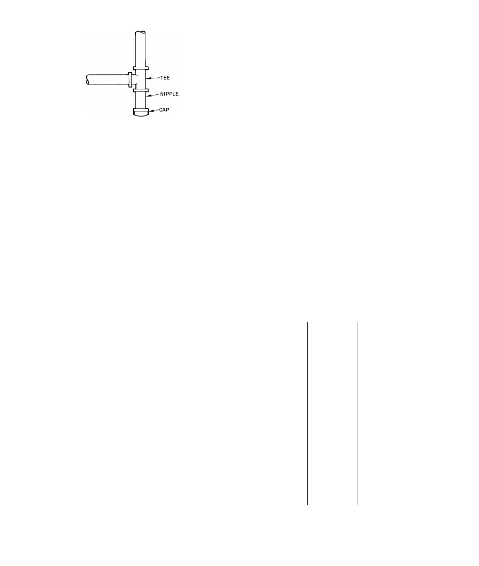
Fig. 7 — Sediment Trap
5.
Install an accessible, external, manual shutoff
valve in gas supply pipe within 6 ft of heating
section. Install a 1/8-in. NPT plugged tapping
that is accessible for test-gage connection imme
diately upstream from gas supply connection to
heating section and downstream from main
manual shutoff valve.
6. Install ground-joint union close to heating sec
tion between gas valve and external manual main
shutoff valve.
7. Pressure-test all gas piping in accordance with
local and national plumbing and gas codes before
connecting piping to unit.
NOTE: When pressure-testing the gas supply
system
after the gas supply piping has been con
nected to the unit gas valve, the supply piping
must be disconnected from the gas valve during
any pressure testing of the piping systems at test
pressure in excess of 0.5 in. wg. When pressure
testing the gas supply piping system at test pres
sures equal to or less than 0.5 in. wg, the unit
heating section must be isolated from the gas
piping system by closing the external main
manual
shutoff
valve
and
slightly
opening
ground-joint union.
CAO'OON; OfisSiabieopciSiiloiìmayoccitr, ps?-
ttcalarly ajtdej
cosditioas» when gas;
aad maììifoìd assentbiy ate foreed o«t of
while cesitiecSsg iaijwopBriy routed»
gas
t-o .gas vidvee Use a bacicap
wcesch wbeti saaktag eosmecisoa to avoid stsais
03R» or dtsiordow of, gas control plpiog,
8. Where permitted by local codes, use an approved
corrugated metal tubing gas connector between
rigid gas piping and gas valve.
WARNING: Never saae a îmtcïi or other o-pen
flaaie when elîeckisg for leaks.
9.
Check for gas leaks at all field-installed and
factory-installed gas lines after all piping connec
tions have been completed. Use soap-and-water
solution (or method specified by local codes and/
or regulations).
Step 3 — Make Duct Connections
— Model
48KH,KL has duct flanges on the supply-and return-
air openings on side of unit. See Fig. 4.
WARNING: The design and installation ofdagt
system mmt he in atx-ordancewttit standards of
Natlonai Fire Protecdon Assoctatioo for tw-
staïiaiton of ncm.~restdencetypeatreoodittoaEiing
and ventilating systems» NFPA Nox9ê; or
residence-type NFPA No. 90 &; aad/ttr h>cai
codes and ordlsaxtces.
Adhere to the following requirements when selec
ting, sizing and installing duct system:
1. Select and size ductwork, supply-air registers and
return-air grilles according to ASHRAE recom
mendations and as presented in Carrier System
Design Manual, Part 2. System airflow must be
within range of temperature rise and external
static pressure shown on unit AGA rating plate.
CAÏJTEON: Whca doct~systcm fasteaiag
holes are drilled into side of Model dSKBXL
mstead of the tmit ddct fiaages, lise extreme
care to avoid panctoriag ood or cod tubes.
2. Use a flexible transition between rigid ductwork
and unit to prevent transmission of vibration.
The transition may be screwed or bolted to duct
flanges. Use suitable gaskets to ensure a weather-
tight and airtight seal.
Table 2 — Filter Sizes (Field Supplied),
Size Sq In.*
STANDARD
CLEANABLE OR
MODEL 48—
DISPOSABLE
HIGH CAPACITY
TYPE
TYPE
KL.018300BE
300
187
KL024300BE
400
257
KH024300BE
400
260
KL030300BE
522
339
KH030300BE
522
339
KL036300BE
576
374
KL036500CE
576
374
KL036600CE
576
374
KH036300BE
583
379
KH036300BF
722
451
KH036500CE
576
374
KH036500CF
694
451
KL042300BE
~
. .. _
43У
KL042500CE
672
437
KH042300BE
672
437
KH042500CE
672
437
KL04830ÒBE
768 ~~
499"
KL048500CE
768
499
KL048600CE
768
499
KH048300BE/BF
768
499
KH048500CE/CF
768
499
KL060300BE
95d
618 ’
KH060300BE/BF
950
618
^Recommended air filter areas shown are based on either the ARI-
rated cooling airflow or the heating airflow at a velocity of 300 fpm
depending on whichever value is larger Air filter pressure drop
should not exceed 0 08 in wgfor unit to produce the rated cooling
performance