Step 2 — make gas piping connections — the – Carrier 48KH User Manual
Page 5
Attention! The text in this document has been recognized automatically. To view the original document, you can use the "Original mode".
#
m
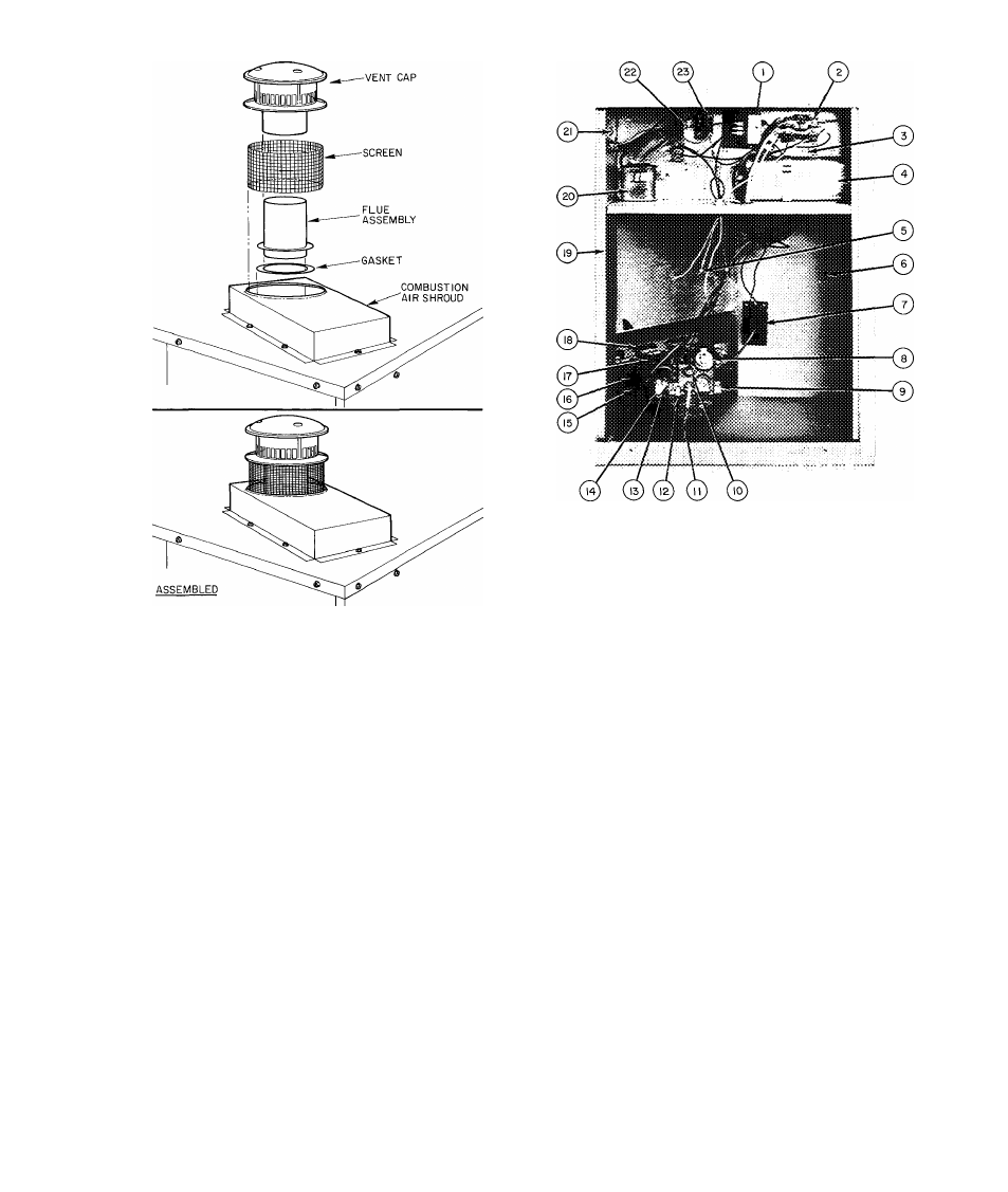
Fig. 5 — Vent Cap Assembly
Step 2 — Make Gas Piping Connections
— The
gas supply pipe enters unit thru access hole provided.
See Fig. 4 for location. The gas connection to unit is
made to the 1/2-in. FPT gas inlet on gas valve. See
Fig. 6 for inlet location.
Install a separate gas supply line that runs directly
from meter to heating section.
Do not use cast-iron
pipe. Check local utility for recommendations con
cerning existing lines. Choose a supply pipe that is
large enough to keep pressure loss as low as practical.
Never use pipe smaller than the 1 / 2-in. FPT gas inlet
on gas valve.
When installing gas supply line, observe local
codes pertaining to gas pipe installations. Refer to
National Fuel Gas Code ANSI Z223.1-1980 or
NFPA 54-1980 in absence of local building codes.
Adhere to following pertinent recommendations:
1. Avoid low spots in long runs of pipe. Grade all
pipe 1 /4 in. in every 15 ft to prevent traps. Grade
all horizontal runs downward to risers. Use risers
to connect to heating section and to meter.
2. Support all piping with appropriate hangers, etc.
Use a minimum of one hanger in every 6 feet. For
pipe sizes larger than 1/2 in., follow recom
mendations of national codes.
7
8
9
10
Control Transformer
11 — Pilot Tube
Compressor Contactor
12 — Model 646A-X Gas
Ground Lug
Valve
Dual Run Capacitor
13 — Pressure Tap Pipe Plug
(for compressor and
14 — Gas Valve Outlet
condenser fan motor)
15 — Gas Manifold
Low-Voltage Pigtail
16 — Gas Burner
Leads
17 — Burner Air Shutter
Compressor/Control
18 — Secondary-Air Shield
Compartment Divider
19 — Blower Flousing
Panel
20 — Evaporator Motor Run
Igniter Module
Capacitor
Manual ON/OFF
21 — Blower/Control Com
Knob
partment Divider
Gas Valve Inlet
Panel
Pipe Plug — LP
22 — Heating Relay
(Propane) unit pres
sure switch mounts
here
23 — Cooling Relay
Fig. 6 — Model 48KL036 — Side View
(Partial) with Access Door Removed
3. Apply joint compound (pipe dope) sparingly and
only to male threads of joint when making pipe
connections. Use only pipe dope that is resistant
to action of liquefied petroleum gases as speci
fied by local and/or national codes.
Never use
pipe thread tape.
4. Install a sediment trap in riser leading to the heat
ing section. See Fig. 7. This drip leg functions as a
trap for dirt and condensate. Install trap where
condensate cannot freeze. Install this sediment
trap by connecting a piping tee to riser leading to
heating section, so that straight-thru section of
tee is vertical. Then, connect capped nipple into
lower end of tee. Extend capped nipple below
level of gas controls.