Tablet. 1 —performance data, Installation step 1 — rig and place unit – Carrier 48KH User Manual
Page 2
Attention! The text in this document has been recognized automatically. To view the original document, you can use the "Original mode".
“V “■
Tablet. 1 —Performance Data
MODEL 48-
KL018300BE
KL024300BE
KH024300BE
KL030300BE
KH030300BE
KL036300BE
KL036500CE
KL036600CE
KH036300BE
KH036300BF
KH036500CE
KH036500CF
KL042300BE
KL042500CE
KH042300BE
КН042500СЁ
KL048300BE
KL048500CE
KL048600CE
KH048300BE
KH048300BF
KH048500CE
KH048500CF
КШббзобвЕ
KH060300BE
KH060300BF
NOMINAL
COOLING
SIZE
01 s'
024
^
j024_^
_
030
030
_
036
036
036
036
036
036
036
042
042
042
_042
048“
048
048
048
048
048
048
^
■
060
060
RATED
HEATING
INPUT
(Btuh)
’^40,000 "
40.000
60.000
40.000
60.000
60,000
60,000
60,000
100,000
125.000
100.000
125.000
6o!ooo
60,000
80,000
80,000
80,000
80,000
80,000
100.000
125.000
100.000
125.000
100.000
120,000
150,000
T
ARI*
SOUND
RATING
8 2
8 2
^ _8_2__
80
80
80
80
80
80
80 ^
8
2
“
8 2
8
2
8 2_^ _
“8 4“'“
84
84
84
84
8.4
8 4^
““““T2
8.2
8 2
*Sound rating per ARI 270-82
210-81 and ARI Standard 270-82. The units are de
sign certified by the American Gas Association
(AGA) for use with natural or LP (propane) gases
with appropriate controls and orifices. See Table 1
for heating input ratings. Models 48KH,KL units
are fully self-contained, combination gas-heating/
electric-cooling units designed for outdoor installa
tion on either a rooftop or ground-level slab.
These units are equipped with an energy-saving
automatic,
intermittent,
electric
spark
ignition
system that does not have a continuously burning
pilot. All units are manufactured with natural gas
controls.
Units are factory charged with R-22 refrigerant.
To install: connect gas supply, air ducts, high- and
low-voltage wiring and condensate drain, and install
a field-supplied air filter in the return-air ductwork.
All units can be connected into existing duct
systems
that are properly sized and designed to
handle an airflow of350 to 450 cfm per each 12,000
Btuh of rated cooling capacity. See Table 7 for cool
ing and heating airflow requirements.
NOTE: When installing any accessory item, see
Installation Instructions packaged with accessory.
L
mpoKtAm—
HEAD BEFORE iMSTMmiS
i This iiisiailatjo?}
jm&t
coBform with:
at^ltcahie local aad natiOfiaJ codes
2, Power soppiy
herte eod j^ase)
to that s|>echjed
ob
. itaa
m
to
ащйшй by
4, itcgsi: to Fig. 4
f
locaiaoos of
miet,
trkal mieis.. coadoiStater drauB, doid сойяео-
and ceqTiised t^^ances. before setdtig
ООЙ JO place,
5. Locate anit -where vent cap wiii be a Basiioam
of 4 it frorn opetta.bfe wtodowa or dtiore.
codes atid with J^aatmid Feei Gas Code
ANSI Z223.
ЫШ
or biFPA
INSTALLATION
Step 1 — Rig and Place Unit
4
-.*Hi*W'r
4
irr>*l*r*iri*yVVV‘i*
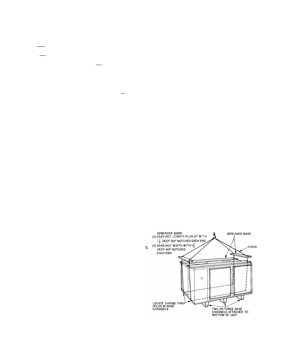
CAUTION- Whea
amt ioih6::3ified, use
spreader bars to protea top atid sides, Blsg^tat
as showo
ki
Fig 2, Use extoMate cauiioo ro pre-
teot daoiags whea movmg ural, Umr mos4
reroaoi to upright pesrtUiKidKrSegaii dggaigaad
movtog operatKios,
ЬШ
ша4
proper cffitbicBsaic drataage,, there^iaiOjidbe:::
groaxid-Jevd pad
cmb
тШ h&
bvol b^ore sehiag шт i& place.
Whoa a iteid-fabsicated sapport t?: used, easore
that support Is jevei atid properly supports auix
and pieaatn
Fig. 2 — 48KH,KL Suggested Rigging