Carrier 48KH User Manual
Combination heating/cooling units, Lajare, Or damage your pfopertj? coasalt a
Attention! The text in this document has been recognized automatically. To view the original document, you can use the "Original mode".
n
Number One
ArConditbning
l\Mer
Division of
Carrier Corporation
Carrier Parkway • Syracuse, N Y 13221
Combination Heating/Cooling Units
Note to Installer: After installation, leave these instructions. Owner’s Manual and Parts
Replacement Guide with equipment owner.
INDEX
Page
SAFETY CONSIDERATIONS.....................................1
GENERAL.......................................................................1,2
INSTALLATION.......................................................... 2-9
Step 1 — Rig and Place Unit..................................2
• ROOFTOP INSTALLATION
• GROUND LEVEL INSTALLATION
• CLEARANCES
• CONDENSATE DISPOSAL
• VENTING
Step 2 — Make Gas Piping Connections .. 5
Step 3 — Make Duct Connections...................... 6
Step 4 — Make Wiring Connections................... 7
• HIGH-VOLTAGE CONNECTIONS
• SPECIAL PROCEDURES FOR
208-V OPERATION
• LOW-VOLTAGE CONNECTIONS
• HEAT ANTICIPATOR SETTING
START-UP.................................................................. 9-18
SERVICE.....................................................................18-21
TROUBLESHOOTING CHARTS ...........................22,23
SAFETY CONSIDERATIONS
WARNING: ïîa|îrojîeTïOfei3tiî3.tîoo»iid.jiE5£îîî.etit, :
îîlieraiïoa, service-mamteroaïîce or tisecaiioatiiit: :
câsfboîî moaoxide poisocdiig, exi^osjoa,
eîectîîc sboeS:
oïbcf oc^Jweîîees. lÿfeicli
m&y
lajare
ym.
or damage your pfopertj? Coasalt a
qaaîîfted îosîaU««, service
or rbs
^
sïippSer for informasou or assistaace-
NOTE: Installation of this unit must conform to the
guidelines presented in these Installation Instruc
tions. Read and become familiar with this publica
tion before starting installation.
Only trained, qualified installers and service
mechanics should install, start-up and service this
equipment. Consult the Owner’s Manual for routine
maintenance. All other operations should be per
formed by trained service personnel.
• Follow all safety codes.
• Wear safety glasses and work gloves.
• Use care in handling, rigging and setting bulky
equipment.
• Observe precautions in these instructions and on
equipment tags, stickers and labels.
WARNING: Do dsseoixaeot olecirtc power
to tilts
'S>
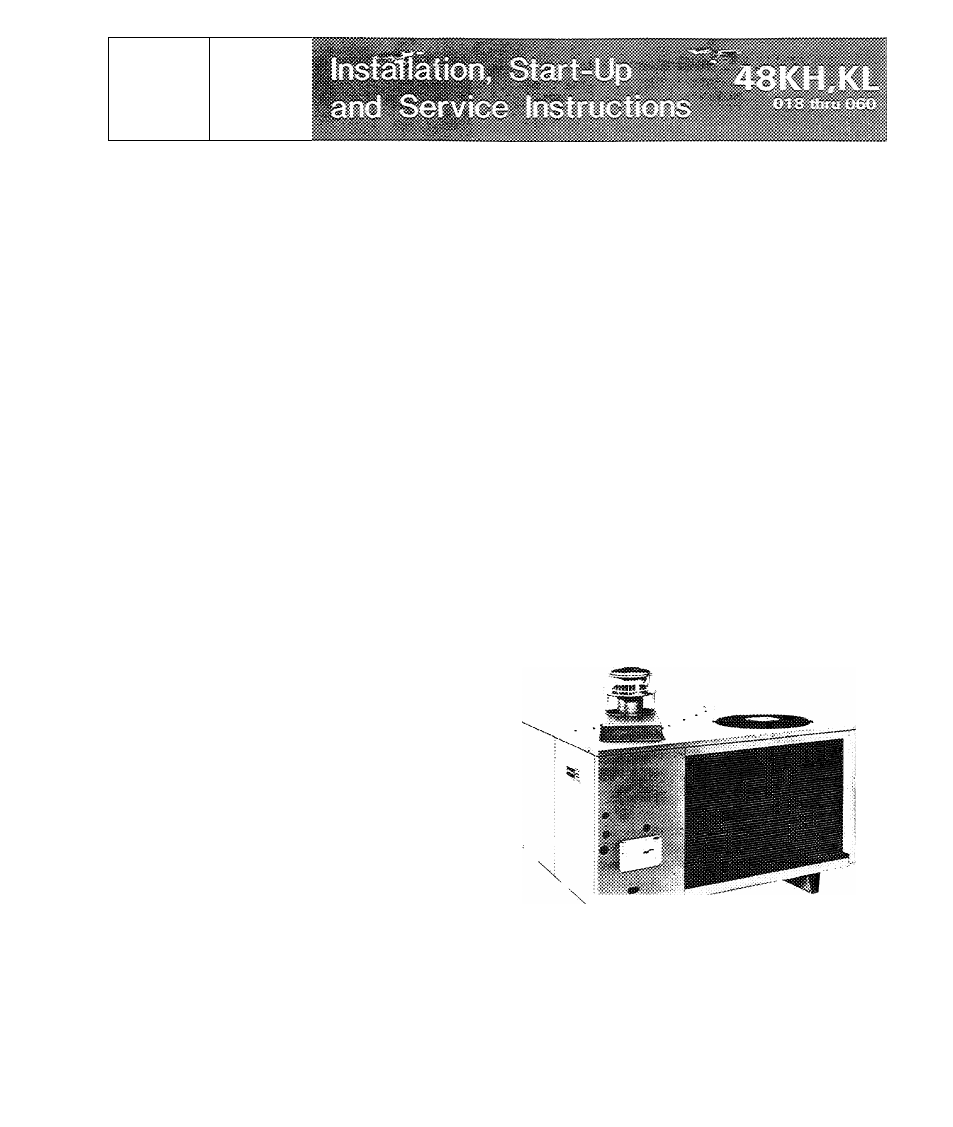
Fig. 1 — Model 48KH-KL
GENERAL
Models 48KH,KL packaged gas/electric units
(see Fig. 1) have been designed and tested in accord
ance with ANSI Z21.47b-1982, ARI Standard
Carrier Corporation 1982
Form 48KH.KL-1SI
Document Outline
- Tablet. 1 —Performance Data
- INSTALLATION Step 1 — Rig and Place Unit
- Weight Data
- Fig. 4 — Dimensions and Clearances (ft-in.)
- Step 2 — Make Gas Piping Connections — The
- Fig. 6 — Model 48KL036 — Side View (Partial) with Access Door Removed
- Step 4 — Make Wiring Connections
- WARNDfG, bnk
- o’
- Fig. 10 — Typical Wiring Diagram (48KH030300 shown)
- if p3ot ialS i.® d.o not
- Cooling Section Start-Up and Adjustments
- «iecfeicai power to . Bo «tire to
- CAOTION: Do clm^ hiowesHiaotoE' lead
- eonE£ercti.
- SERVICE
- Top Removal
- Air Filter
- Kev«r ase a îmîdj or other flame ÎÎ& chock for gas leaks.
- Condenser Fan
- CAUTiONc iCeftp «»Eid^Ei&er fail of all o&stiiBctk>iJs.iooiJsani pr