Carrier 48KH User Manual
Page 3
Attention! The text in this document has been recognized automatically. To view the original document, you can use the "Original mode".
rooftop
installation
CAUTTONc Whfirc bstaiSng amt
oh
à
rooftop.
When installing a Model48KH,KL end discharge
unit with a field-supplied downflow plenum, a field-
supplied roof-mounting curb must be installed on
and flashed into roof before unit installation. When
installing a Model 48KH,KL end discharge unit
without a downflow plenum, place unit on a level
base that provides proper support. On flat roofs be
sure unit is located at least 4 in. above highest ex
pected water level on roof to prevent flooding.
Consult
local
codes
for
additional
installation
requirements.
GROUND LEVEL INSTALLATION — Place unit
on a solid, level concrete pad that is a minimum
of 4 in. thick and that extends approximately 2 in.
beyond casing on all sides of unit. Do not secure unit
to pad
except when required by local codes.
CLEARANCES — Required minimum operating
and service clearances are shown in Fig. 4 for pro
viding adequate combustion, ventilation and con
denser air.
CAin iON: Do aot restrici
cmdtass&v
asrilo«?,
A» mi
restrbtion at either oHtdoor-'aif inkst
emSfo SHtiace of ifee oa.id.oor
coii)
or fea. dis
charge caa bo dotriateatai to coca^ssor Bfe.
Condenser fan discharges thru top of unit. Ensure
that fan discharge does not recirculate to condenser
coil. Do not locate unit in either a corner or under a
complete overhead obstruction. Minimum clearance
under a partial overhang (such asa typical house roof
overhang) is 3 ft above vent cap. Maximum hori
zontal extension of a partial overhang must not
exceed 4 feet.
Do not locate unit where water, falling ice or snow
from an overhang or roof will damage or flood the
unit. Do not locate unit where grass, shrubs or other
plants will interfere with the airflow either into or
out of unit. Do not install unit on carpeting, tile or
other
combustible
material
other
than
wood
flooring.
CONDENSATE DISPOSAL
NOTE: Be sure condensate water disposal methods
comply with local codes, restrictions and practices.
Models 48KH,KL dispose of condensate water
thru a 3/4-in. MPT drain fitting. See Fig. 4 for
location.
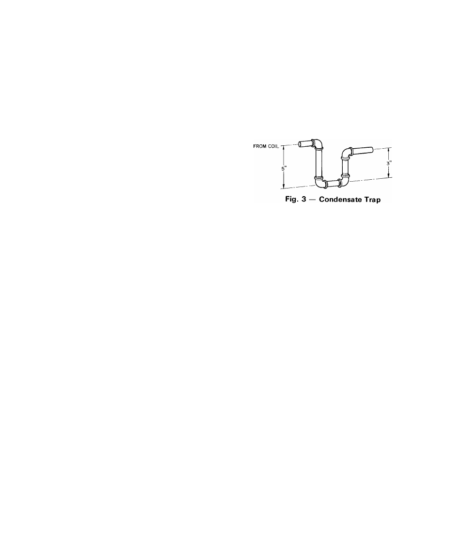
Install a 3-in. trap at the drain fitting to ensure
proper drainage. See Fig. 3. Make sure trap outlet
is at least 2 in. lower than unit drain pan connection
to prevent pan from overflowing. Prime trap with
water.
If installation requires draining the condensate
water away from unit, connect a drain tube using a
minimum of 7/8-in. OD copper tubing, 3/4-in.
galvanized pipe or 7/8-in. plastic pipe.
Do not
undersize the tube. Pitch drain tube downward at a
slope at least 1 in. for every 10 ft of horizontal run.
Be sure to check drain tube for leaks.
Condensate water can be drained directly onto
roof in rooftop installations (where permitted) or
onto a gravel apron in ground level installations.
When using a gravel apron, make sure it slopes away
from the unit.
TO DRAIN
VENTING — The vent cap, combustion air shroud
and flue assembly are shipped in either the blower or
control compartment. Vent screen is taped to blower
housing. Remove access doors to locate assemblies.
See Fig. 4 for door locations.
C-AUTiOKt V
giroper ïeïîttïîg,
fee si-
stalled as Îîî^icated iielovs^.
NOTE: Screw holes in flue assembly and unit top
are positioned to ensure proper orientation when
installed. Refer to Fig. 5 and install vent cap as
follows:
1. Place combustion air shroud over combustion air
opening in unit top, and line up screw holes in
shroud with holes in top. Secure shroud to top,
using screws with rubber washers (provided).
2. Plaee gasket and flue assembly thru hole in com
bustion air shroud, orient screw holes in base of
flue assembly with holes in unit top, and secure
gasket and flue assembly to unit top, using screws
provided.
3. Form flat wire screen (provided) into circular
shape around protruding lip of combustion-air
shroud and bend wire ends thru holes of screen
mesh to secure screen in place. Make sure that no
sharp edges are left exposed.
4. Place vent cap sleeve inside flue assembly. Orient
spring clip of vent cap with slot in assembly. Be
sure clip snaps into slot to secure clip onto
assembly.